Alarms and security schematics
 These are two - easy to build - relay-based alarms. You can use them to protect your motorcycle - but they have many more applications. If you use relays with 6-volt coils - they'll protect your "Classic Bike". Both alarms are very small. The completed boards occupy about half a cubic-inch - 8 cc. The standby current is zero - so they won't drain your battery....
[read more]
These are two - easy to build - relay-based alarms. You can use them to protect your motorcycle - but they have many more applications. If you use relays with 6-volt coils - they'll protect your "Classic Bike". Both alarms are very small. The completed boards occupy about half a cubic-inch - 8 cc. The standby current is zero - so they won't drain your battery....
[read more]
![]() This is simple transistor based motorcycle alarm. The circuit features a timed output and automatic reset. It can be operated manually using a key-switch or a hidden switch. By adding an external relay, it will set itself automatically - and/or immobilize the machine - every time you turn-off the ignition. It's easily adapted for a 6-volt system - so it will protect your "Classic Bike"...
[read more]
This is simple transistor based motorcycle alarm. The circuit features a timed output and automatic reset. It can be operated manually using a key-switch or a hidden switch. By adding an external relay, it will set itself automatically - and/or immobilize the machine - every time you turn-off the ignition. It's easily adapted for a 6-volt system - so it will protect your "Classic Bike"...
[read more]
 This circuit features an intermittent siren output and automatic reset. It can be operated manually using a key-switch or a hidden switch; but it can also be wired to set itself automatically when you turn-off the ignition. By adding external relays you can immobilize the bike, flash the lights etc. It's easily adapted for a 6-volt system - so it will protect your "Classic Bike"...
[read more]
This circuit features an intermittent siren output and automatic reset. It can be operated manually using a key-switch or a hidden switch; but it can also be wired to set itself automatically when you turn-off the ignition. By adding external relays you can immobilize the bike, flash the lights etc. It's easily adapted for a 6-volt system - so it will protect your "Classic Bike"...
[read more]
 This circuit features an intermittent siren output and automatic reset. It can be operated manually using a key-switch or a hidden switch; but it can also be wired to set itself automatically when you turn-off the ignition. By adding external relays you can immobilize the bike, flash the lights etc....
[read more]
This circuit features an intermittent siren output and automatic reset. It can be operated manually using a key-switch or a hidden switch; but it can also be wired to set itself automatically when you turn-off the ignition. By adding external relays you can immobilize the bike, flash the lights etc....
[read more]
![]() This circuit features a timed output and automatic reset. It can be operated manually using a key-switch or a hidden switch. By adding an external relay, it will set itself automatically - and/or immobilize the machine - every time you turn-off the ignition. It's easily adapted for a 6-volt system - so it will protect your "Classic Bike"....
[read more]
This circuit features a timed output and automatic reset. It can be operated manually using a key-switch or a hidden switch. By adding an external relay, it will set itself automatically - and/or immobilize the machine - every time you turn-off the ignition. It's easily adapted for a 6-volt system - so it will protect your "Classic Bike"....
[read more]
 Like the first two Hijack Alarms - if a door is opened while the ignition is switched on - the circuit will trip. And after a few minutes delay - when the thief is at a safe distance - the Siren will sound. But this time the engine does not go on to fail automatically. Instead - it will continue to run until the thief turns off the ignition. Then the engine will not re-start....
[read more]
Like the first two Hijack Alarms - if a door is opened while the ignition is switched on - the circuit will trip. And after a few minutes delay - when the thief is at a safe distance - the Siren will sound. But this time the engine does not go on to fail automatically. Instead - it will continue to run until the thief turns off the ignition. Then the engine will not re-start....
[read more]
 This car alarm circuit features Exit and Entry delays, an instant alarm zone, an intermittent siren output and automatic Reset. By adding external relays you can immobilize the vehicle and flash the lights....
[read more]
This car alarm circuit features Exit and Entry delays, an instant alarm zone, an intermittent siren output and automatic Reset. By adding external relays you can immobilize the vehicle and flash the lights....
[read more]
 The circuit consists of a small PIC microcontroller, assembly program,
and a few other parts to detect a switch closure from an open door, window,
or manual push button and then dial the cell phone number, and transmit a
steady tone to indicate the source of the call. The circuit uses the pulse
dialing system to interrupt the line connection a number of times to
indicate each digit....
[read more]
The circuit consists of a small PIC microcontroller, assembly program,
and a few other parts to detect a switch closure from an open door, window,
or manual push button and then dial the cell phone number, and transmit a
steady tone to indicate the source of the call. The circuit uses the pulse
dialing system to interrupt the line connection a number of times to
indicate each digit....
[read more]
 The digital lock shown below uses 4 common logic ICs to allow controlling a relay by entering a 4 digit number on a keypad. The first 4 outputs from the CD4017 decade counter (pins 3,2,4,7) are gated together with 4 digits from a keypad so that as the keys are depressed in the correct order, the counter will advance....
[read more]
The digital lock shown below uses 4 common logic ICs to allow controlling a relay by entering a 4 digit number on a keypad. The first 4 outputs from the CD4017 decade counter (pins 3,2,4,7) are gated together with 4 digits from a keypad so that as the keys are depressed in the correct order, the counter will advance....
[read more]
 A different circuit of electronic lock very simple, one and does not need a lot of materials in order to it is manufactured....
[read more]
A different circuit of electronic lock very simple, one and does not need a lot of materials in order to it is manufactured....
[read more]
 It is a relatively simple circuit of electronic lock of safety with code of 7 digits. It should is given attention in the time that will be stepped the keys, that shape code and it does not exist it delays. With the right step of keys and if code is right then is activated exit Q7 for roughly 4 seconds, driving the transistor Q2, which with the line can drive one relay, for the opening of door, or any other circuit. With LED D we can have optical clue of activation. The code of circuit, as it has been given have been:1704570 but can change, if we change the connections between in the exits of IC1 and the switches....
[read more]
It is a relatively simple circuit of electronic lock of safety with code of 7 digits. It should is given attention in the time that will be stepped the keys, that shape code and it does not exist it delays. With the right step of keys and if code is right then is activated exit Q7 for roughly 4 seconds, driving the transistor Q2, which with the line can drive one relay, for the opening of door, or any other circuit. With LED D we can have optical clue of activation. The code of circuit, as it has been given have been:1704570 but can change, if we change the connections between in the exits of IC1 and the switches....
[read more]
 This circuit is designed to operate an electrical door-release mechanism - but it will have other applications. When you enter the four-digit code of your choice - the relay will energize for a preset time period. Use the relay contacts to power the release mechanism. The standby current is virtually zero - so battery power is a realistic option....
[read more]
This circuit is designed to operate an electrical door-release mechanism - but it will have other applications. When you enter the four-digit code of your choice - the relay will energize for a preset time period. Use the relay contacts to power the release mechanism. The standby current is virtually zero - so battery power is a realistic option....
[read more]
 This is a simplified version of the 4-Digit Keypad Controlled Switch. I have modified the design to reduce the complexity of the circuit - and the number of components required. As a result - the code is somewhat less secure. However, there should be lots of situations where it will still be adequate....
[read more]
This is a simplified version of the 4-Digit Keypad Controlled Switch. I have modified the design to reduce the complexity of the circuit - and the number of components required. As a result - the code is somewhat less secure. However, there should be lots of situations where it will still be adequate....
[read more]
 This is a Universal version of the Four-Digit Alarm Control Keypad. I have modified the design to free up the relay contacts. This allows the circuit to operate as a general-purpose switch. I've used a SPCO/SPDT relay - but you can use a multi-pole relay if you wish....
[read more]
This is a Universal version of the Four-Digit Alarm Control Keypad. I have modified the design to free up the relay contacts. This allows the circuit to operate as a general-purpose switch. I've used a SPCO/SPDT relay - but you can use a multi-pole relay if you wish....
[read more]
 This alarm circuit was designed to monitor a mains-powered smoke detector located in a shed (which is used to house dog kennels). It provides complete isolation from the mains so that low-voltage (12V) cabling could be run to the alarm circuit which is located inside the house. In operation, the alarm signal (I) from the smoke detector is rectified using bridge rectifier BR1 and then fed to optoiso lator OPTO1 via resistor R3. This in turn drives the gate of SCR1 which turns on and activates a piezo siren with inbuilt oscillator....
[read more]
This alarm circuit was designed to monitor a mains-powered smoke detector located in a shed (which is used to house dog kennels). It provides complete isolation from the mains so that low-voltage (12V) cabling could be run to the alarm circuit which is located inside the house. In operation, the alarm signal (I) from the smoke detector is rectified using bridge rectifier BR1 and then fed to optoiso lator OPTO1 via resistor R3. This in turn drives the gate of SCR1 which turns on and activates a piezo siren with inbuilt oscillator....
[read more]
 A complementary transistor pair (Q2 & Q3) is wired as a high efficiency oscillator, directly driving the loudspeaker. Q1 ensures a full charge of C2 when power is applied to the circuit. Pressing on P1, C2 gradually discharges through R8: the circuit starts oscillating at a low frequency that increases slowly until a high steady tone is reached and kept indefinitely. When P1 is released, the output tone frequency decreases slowly as C2 is charged to the battery positive voltage through R6 and the Base-Emitter junction of Q2. When C2 is fully charged the circuit stops oscillating, reaching a stand-by status....
[read more]
A complementary transistor pair (Q2 & Q3) is wired as a high efficiency oscillator, directly driving the loudspeaker. Q1 ensures a full charge of C2 when power is applied to the circuit. Pressing on P1, C2 gradually discharges through R8: the circuit starts oscillating at a low frequency that increases slowly until a high steady tone is reached and kept indefinitely. When P1 is released, the output tone frequency decreases slowly as C2 is charged to the battery positive voltage through R6 and the Base-Emitter junction of Q2. When C2 is fully charged the circuit stops oscillating, reaching a stand-by status....
[read more]
 This circuit, enclosed in a small plastic box, can be placed into a bag or handbag. A small magnet is placed close to the reed switch and connected to the hand or the clothes of the person carrying the bag by means of a tiny cord. If the bag is snatched abruptly, the magnet looses its contact with the reed switch, SW1 opens, the circuit starts oscillating and the loudspeaker emits a loud alarm sound. A complementary transistor-pair is wired as a high efficiency oscillator, directly driving a small loudspeaker. Low part-count and 3V battery supply allow a very compact construction....
[read more]
This circuit, enclosed in a small plastic box, can be placed into a bag or handbag. A small magnet is placed close to the reed switch and connected to the hand or the clothes of the person carrying the bag by means of a tiny cord. If the bag is snatched abruptly, the magnet looses its contact with the reed switch, SW1 opens, the circuit starts oscillating and the loudspeaker emits a loud alarm sound. A complementary transistor-pair is wired as a high efficiency oscillator, directly driving a small loudspeaker. Low part-count and 3V battery supply allow a very compact construction....
[read more]
 Protect your valuable laptop against theft using this miniature alarm generator. Fixed in-side the laptop case, it will sound a loud alarm when someone tries to take the laptop. This highly sensitive circuit uses a homemade tilt switch to activate the alarm through tilting of the laptop case. The circuit uses readily available components and can be assembled on a small piece of Vero board or a general-purpose PCB....
[read more]
Protect your valuable laptop against theft using this miniature alarm generator. Fixed in-side the laptop case, it will sound a loud alarm when someone tries to take the laptop. This highly sensitive circuit uses a homemade tilt switch to activate the alarm through tilting of the laptop case. The circuit uses readily available components and can be assembled on a small piece of Vero board or a general-purpose PCB....
[read more]
 If you use a lamp with a motion sensor for outdoor lighting, the original electrical switch is actually no longer necessary. If you replace the switch with the circuit described here, an acoustical signal will be generated each time the outdoor lamp is switched on. It’s thus somewhere between an alarm and a doorbell. The operating principle is simple. A circuit that causes a voltage drop of only a couple of volts is connected in series with the lamp. As the circuit needs a DC voltage, the current for the lamp is passed through a bridge rectifier....
[read more]
If you use a lamp with a motion sensor for outdoor lighting, the original electrical switch is actually no longer necessary. If you replace the switch with the circuit described here, an acoustical signal will be generated each time the outdoor lamp is switched on. It’s thus somewhere between an alarm and a doorbell. The operating principle is simple. A circuit that causes a voltage drop of only a couple of volts is connected in series with the lamp. As the circuit needs a DC voltage, the current for the lamp is passed through a bridge rectifier....
[read more]
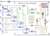 This Keypad is suitable for the Modular Burglar Alarm. However, it has other applications. Entering the First Four Digits of your chosen Five-Digit code - will energize the relay. Entering the Full Five-Digit code - will de-energize it....
[read more]
This Keypad is suitable for the Modular Burglar Alarm. However, it has other applications. Entering the First Four Digits of your chosen Five-Digit code - will energize the relay. Entering the Full Five-Digit code - will de-energize it....
[read more]
 This Keypad is suitable for the Modular Burglar Alarm. However, it has other applications. Pressing a single key will energize the relay. Entering the Four-Digit code of your choice will de-energize it....
[read more]
This Keypad is suitable for the Modular Burglar Alarm. However, it has other applications. Pressing a single key will energize the relay. Entering the Four-Digit code of your choice will de-energize it....
[read more]
 This is a single zone alarm - with independently adjustable Exit, Entry and Siren Cut-Off timers. When the alarm is activated its Siren will sound once - for up to 20-minutes. Then it will switch off and remain off. If you wish - you can use a mains power supply. But the extremely low standby current makes battery power a realistic option....
[read more]
This is a single zone alarm - with independently adjustable Exit, Entry and Siren Cut-Off timers. When the alarm is activated its Siren will sound once - for up to 20-minutes. Then it will switch off and remain off. If you wish - you can use a mains power supply. But the extremely low standby current makes battery power a realistic option....
[read more]
 This is an enhanced version of the simple Garage/Shed Alarm. The Entry and Exit delays have been increased to about 30-seconds - and I've added a timed Siren cut-off and automatic Reset. I've also replaced the LED with an entry Buzzer. These enhancements mean that the new version will have a much wider application....
[read more]
This is an enhanced version of the simple Garage/Shed Alarm. The Entry and Exit delays have been increased to about 30-seconds - and I've added a timed Siren cut-off and automatic Reset. I've also replaced the LED with an entry Buzzer. These enhancements mean that the new version will have a much wider application....
[read more]
 This is a basic single-zone burglar alarm circuit. Its features include automatic Exit and Entry delays - and an optional Siren Cut-Off timer. It has an extremely small standby current. This makes it ideal for battery-powered operation. Use it in your caravan, mobile home, lock-up, or anywhere mains power is not available....
[read more]
This is a basic single-zone burglar alarm circuit. Its features include automatic Exit and Entry delays - and an optional Siren Cut-Off timer. It has an extremely small standby current. This makes it ideal for battery-powered operation. Use it in your caravan, mobile home, lock-up, or anywhere mains power is not available....
[read more]
 This circuit will let you know when something that should be kept closed - has in fact been left open. Attach it to a Fire-Door. It will allow you to pass through the door as usual. However, if it's left open for more than 30-seconds or so - the buzzer will sound....
[read more]
This circuit will let you know when something that should be kept closed - has in fact been left open. Attach it to a Fire-Door. It will allow you to pass through the door as usual. However, if it's left open for more than 30-seconds or so - the buzzer will sound....
[read more]
 Attach this circuit to the door of an unattended shop - or reception area - and the sound of the buzzer will tell you when you have a customer. Add a siren - and it becomes a simple intruder alarm. Photo...
[read more]
Attach this circuit to the door of an unattended shop - or reception area - and the sound of the buzzer will tell you when you have a customer. Add a siren - and it becomes a simple intruder alarm. Photo...
[read more]
![]() This is a selection of simple self-contained transistor based alarm circuits - complete with photographs. They are designed around the Complementary Latch. All may be triggered by both normally-open and normally-closed switches. They have a very low standby current - and are ideal for battery operation....
[read more]
This is a selection of simple self-contained transistor based alarm circuits - complete with photographs. They are designed around the Complementary Latch. All may be triggered by both normally-open and normally-closed switches. They have a very low standby current - and are ideal for battery operation....
[read more]
 This is a selection of small self-contained alarm circuits. They have a very low standby current; and are suitable for battery operation. Some are triggered by normally-open and normally-closed switches. Some react to changes in light or temperature. The result is a variety of output times and patterns....
[read more]
This is a selection of small self-contained alarm circuits. They have a very low standby current; and are suitable for battery operation. Some are triggered by normally-open and normally-closed switches. Some react to changes in light or temperature. The result is a variety of output times and patterns....
[read more]
 This is a single zone alarm - with automatic exit, entry and siren cut-off timers. It will accommodate all the usual types of normally-closed input devices - such as magnetic reed contacts, foil tape, PIRs etc. But it's easy to add a normally-open trigger. When the alarm is activated - the siren will sound for a fixed length of time. Then it will switch off - and remain off. The alarm will not reactivate. The Circuit Description offers a good introduction to the Cmos 4060 and the SCR....
[read more]
This is a single zone alarm - with automatic exit, entry and siren cut-off timers. It will accommodate all the usual types of normally-closed input devices - such as magnetic reed contacts, foil tape, PIRs etc. But it's easy to add a normally-open trigger. When the alarm is activated - the siren will sound for a fixed length of time. Then it will switch off - and remain off. The alarm will not reactivate. The Circuit Description offers a good introduction to the Cmos 4060 and the SCR....
[read more]
 This circuit features automatic Exit/Entry delays, timed Bell Cut-off and System Reset. It will accommodate the usual normally-closed input devices (Magnetic Reed contacts, Micro Switches, Foil Tape and PIRs). And - with a simple modification - a normally-open trigger may be added....
[read more]
This circuit features automatic Exit/Entry delays, timed Bell Cut-off and System Reset. It will accommodate the usual normally-closed input devices (Magnetic Reed contacts, Micro Switches, Foil Tape and PIRs). And - with a simple modification - a normally-open trigger may be added....
[read more]