Tone and volume control schematics
 This unique property makes the ‘paraphase’ configuration of interest if only treble or bass needs to be adjusted - it is not possible to adjust both at the same time! Essentially, it’s the difference in setting of the tone controls that determines the slope of the frequency response, and the degree of bass/treble correction. The circuit is simplicity itself, based on two networks C1-C2-C3/R9-R10-R11 and C5-C6-C7/R12-R13-R14....
[read more]
This unique property makes the ‘paraphase’ configuration of interest if only treble or bass needs to be adjusted - it is not possible to adjust both at the same time! Essentially, it’s the difference in setting of the tone controls that determines the slope of the frequency response, and the degree of bass/treble correction. The circuit is simplicity itself, based on two networks C1-C2-C3/R9-R10-R11 and C5-C6-C7/R12-R13-R14....
[read more]
 This circuit could be used for replacing your manual volume control in a stereo amplifier. In this circuit, push-to-on switch SW1 controls the forward (volume increase) operation of both channels while a similar switch SW2 controls reverse (volume decrease) operation of both channels. A readily available IC from Dallas semiconductor, DS1669 is used here....
[read more]
This circuit could be used for replacing your manual volume control in a stereo amplifier. In this circuit, push-to-on switch SW1 controls the forward (volume increase) operation of both channels while a similar switch SW2 controls reverse (volume decrease) operation of both channels. A readily available IC from Dallas semiconductor, DS1669 is used here....
[read more]
 In order to obtain a good audio reproduction at different listening levels, a different tone-controls setting should be necessary to suit the well known behavior of the human ear. In fact, the human ear sensitivity varies in a non-linear manner through the entire audible frequency band, as shown by Fletcher-Munson curves....
[read more]
In order to obtain a good audio reproduction at different listening levels, a different tone-controls setting should be necessary to suit the well known behavior of the human ear. In fact, the human ear sensitivity varies in a non-linear manner through the entire audible frequency band, as shown by Fletcher-Munson curves....
[read more]
 The circuit of graphic equalizer, allocates ten adjusting potesometer , that each one from them affects in a predetermined area of frequencies, the central frequency of which abstains a octave (double), from the central frequencies of her neighbouring regions. Each unit has common materials with remainder and it differs only in the capacity of capacitors that constitutes the filter in each unit....
[read more]
The circuit of graphic equalizer, allocates ten adjusting potesometer , that each one from them affects in a predetermined area of frequencies, the central frequency of which abstains a octave (double), from the central frequencies of her neighbouring regions. Each unit has common materials with remainder and it differs only in the capacity of capacitors that constitutes the filter in each unit....
[read more]
 The EQ-2 it is a circuit of graphic equalizer 6 band of regulation. Each band is regulated from the potesometers RV1-6, that are, for better optical indicate of regulations, Fader. This does not mean that we cannot him replace with simply potesometer. In the center of regulation potesometer, the gain is null (flat), but in terminal has +/- 15 db, boost or cutting off, respectively. For stereo operation, it will be supposed two times....
[read more]
The EQ-2 it is a circuit of graphic equalizer 6 band of regulation. Each band is regulated from the potesometers RV1-6, that are, for better optical indicate of regulations, Fader. This does not mean that we cannot him replace with simply potesometer. In the center of regulation potesometer, the gain is null (flat), but in terminal has +/- 15 db, boost or cutting off, respectively. For stereo operation, it will be supposed two times....
[read more]
 Other one unit of graphic EQ. five bands. The basic difference with the other circuits is, that I use instead of IC, transistor and the power supply, go up in +/- 24V DC, ensuring low distortion and bigger margins of overloading. With switch S1, we can isolate the EQ. inside or except operation, leaving the musical signal to pass without no alteration....
[read more]
Other one unit of graphic EQ. five bands. The basic difference with the other circuits is, that I use instead of IC, transistor and the power supply, go up in +/- 24V DC, ensuring low distortion and bigger margins of overloading. With switch S1, we can isolate the EQ. inside or except operation, leaving the musical signal to pass without no alteration....
[read more]
 A classic circuit of regulation of tone of three way, with which we can regulate low, mid and high frequencies, of acoustic signal. The boost/cut can be regulated in the range of ± 18 dB/oct. In the circuit the supply is ± 15V, but can be also supplied with alone supply + 9 until + 30...
[read more]
A classic circuit of regulation of tone of three way, with which we can regulate low, mid and high frequencies, of acoustic signal. The boost/cut can be regulated in the range of ± 18 dB/oct. In the circuit the supply is ± 15V, but can be also supplied with alone supply + 9 until + 30...
[read more]
 The circuit constitutes a natural extension of Mic-Line balance unit, but can be adapted to any other audio circuit. It is made up of two units in the series : A) A classic unit bass/ Treble and B) a parametric unit of mid frequencies. Both units can also be used autonomously or each one separately, with the required buffer unit, from previous and subsequent circuits....
[read more]
The circuit constitutes a natural extension of Mic-Line balance unit, but can be adapted to any other audio circuit. It is made up of two units in the series : A) A classic unit bass/ Treble and B) a parametric unit of mid frequencies. Both units can also be used autonomously or each one separately, with the required buffer unit, from previous and subsequent circuits....
[read more]
 This circuit is design, in order to is heard the voice above the music. Useful for DJ, for small radio stations, for statements above the music, in shops etc. Also we can him use in applications that we want to handle some unit with our voice. As it has the circuit has become forecast for stereo music and monophonic microphone, but can be modified and be adapted in the needs or in the use that we want, him we use....
[read more]
This circuit is design, in order to is heard the voice above the music. Useful for DJ, for small radio stations, for statements above the music, in shops etc. Also we can him use in applications that we want to handle some unit with our voice. As it has the circuit has become forecast for stereo music and monophonic microphone, but can be modified and be adapted in the needs or in the use that we want, him we use....
[read more]
 Many times we needed to use a simple circuit of preamplifier, with few components and facility of made. This circuit use a opamp. the Motorola, TCA5550, that contains a double amplifier, as outputs for the adjust of volume, balance, treble and bass. These adjustment of all parameters become from a line monophonic linear potesometers, increasing by far the facility of manufacture. The placement these potesometers should become as much as possible, more near in IC1, so that is minimised the noise. The circuit does not require big current in order to it work....
[read more]
Many times we needed to use a simple circuit of preamplifier, with few components and facility of made. This circuit use a opamp. the Motorola, TCA5550, that contains a double amplifier, as outputs for the adjust of volume, balance, treble and bass. These adjustment of all parameters become from a line monophonic linear potesometers, increasing by far the facility of manufacture. The placement these potesometers should become as much as possible, more near in IC1, so that is minimised the noise. The circuit does not require big current in order to it work....
[read more]
 In order to obtain a good audio reproduction at different listening levels, a different tone-controls setting should be necessary to suit the well known behaviour of the human ear. In fact, the human ear sensitivity varies in a non-linear manner through the entire audible frequency band, as shown by Fletcher-Munson curves.
A simple approach to this problem can be done inserting a circuit in the preamplifier stage, capable of varying automatically the frequency response of the entire audio chain in respect to the position of the control knob, in order to keep ideal listening conditions under different listening levels....
[read more]
In order to obtain a good audio reproduction at different listening levels, a different tone-controls setting should be necessary to suit the well known behaviour of the human ear. In fact, the human ear sensitivity varies in a non-linear manner through the entire audible frequency band, as shown by Fletcher-Munson curves.
A simple approach to this problem can be done inserting a circuit in the preamplifier stage, capable of varying automatically the frequency response of the entire audio chain in respect to the position of the control knob, in order to keep ideal listening conditions under different listening levels....
[read more]
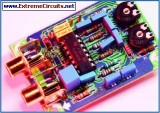
 This digital volume control has no pot to wear out and introduces almost no noise in the circuit. Instead, the volume is controlled by pressing UP and DOWN buttons. This simple circuit would be a great touch to any home audio project....
[read more]
This digital volume control has no pot to wear out and introduces almost no noise in the circuit. Instead, the volume is controlled by pressing UP and DOWN buttons. This simple circuit would be a great touch to any home audio project....
[read more]
 The LM1036 is a DC controlled tone (bass/treble), volume and balance circuit for stereo applications in car radio, TV and audio systems. An additional control input allows loudness compensation to be simply effected. Four control inputs provide control of the bass, treble, balance and volume functions through application of DC voltages from a remote control system or, alternatively, from four potentiometers which may be biased from a zener regulated supply provided on the circuit....
[read more]
The LM1036 is a DC controlled tone (bass/treble), volume and balance circuit for stereo applications in car radio, TV and audio systems. An additional control input allows loudness compensation to be simply effected. Four control inputs provide control of the bass, treble, balance and volume functions through application of DC voltages from a remote control system or, alternatively, from four potentiometers which may be biased from a zener regulated supply provided on the circuit....
[read more]