Miscellaneous oscillator schematics
 If you are the proud owner of an old oscilloscope tube, you may be interested in using it once more for its original purpose. All you need are the right voltages on the right pins: in practice you may need to peer closely inside to find out which pins on the base correspond to the acceleration and deflection electrodes, in particular if there is no part number to be seen on the tube. The tube we had for experimental purposes was a 7 cm model of unknown provenance....
[read more]
If you are the proud owner of an old oscilloscope tube, you may be interested in using it once more for its original purpose. All you need are the right voltages on the right pins: in practice you may need to peer closely inside to find out which pins on the base correspond to the acceleration and deflection electrodes, in particular if there is no part number to be seen on the tube. The tube we had for experimental purposes was a 7 cm model of unknown provenance....
[read more]
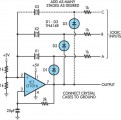 This oscillator circuit permits crystals to be electronically switched by logic commands. The circuit is best understood by initially ignoring all crystals. Furthermore, assume that all diodes are shorts and their associated 1kO resistors open. The two 1kO resistors at the non-inverting input of IC1 (LT1016) set the output to half the supply, ie, +2.5V. The RC network from the output to pin 3 sets up phase-shifted feedback and the circuit looks like a wide-band unity gain follower at DC. When crystal X1 is inserted (remember, D1 is temporarily shorted) positive feedback occurs and oscillation commences at the crystal’s resonant frequency....
[read more]
This oscillator circuit permits crystals to be electronically switched by logic commands. The circuit is best understood by initially ignoring all crystals. Furthermore, assume that all diodes are shorts and their associated 1kO resistors open. The two 1kO resistors at the non-inverting input of IC1 (LT1016) set the output to half the supply, ie, +2.5V. The RC network from the output to pin 3 sets up phase-shifted feedback and the circuit looks like a wide-band unity gain follower at DC. When crystal X1 is inserted (remember, D1 is temporarily shorted) positive feedback occurs and oscillation commences at the crystal’s resonant frequency....
[read more]
 This two-transistor white noise generator has a surprising feature – about 30dB more noise than the more traditional designs. Q1 and Q2 can be any small-signal transistors with a beta of up to 400. The reverse-biased emitter-base junction of Q1 provides the noise source, which is fed into the base of Q2. Q2 forms a simple amplifier with a gain of 45dB. The improved output level is due mainly to the inclusion of C1, which provides a low-impedance AC source to the noise source while not disturbing the DC bias of Q1....
[read more]
This two-transistor white noise generator has a surprising feature – about 30dB more noise than the more traditional designs. Q1 and Q2 can be any small-signal transistors with a beta of up to 400. The reverse-biased emitter-base junction of Q1 provides the noise source, which is fed into the base of Q2. Q2 forms a simple amplifier with a gain of 45dB. The improved output level is due mainly to the inclusion of C1, which provides a low-impedance AC source to the noise source while not disturbing the DC bias of Q1....
[read more]
 Here is a simple triangle/squarewave generator using a common 1458 dual op-amp that can be used from very low frequencies to about 10 Khz. The time interval for one half cycle is about R*C and the outputs will supply about 10 milliamps of current. Triangle amplitude can be altered by adjusting the 47K resistor, and waveform offset can be removed by adding a capacitor in series with the output....
[read more]
Here is a simple triangle/squarewave generator using a common 1458 dual op-amp that can be used from very low frequencies to about 10 Khz. The time interval for one half cycle is about R*C and the outputs will supply about 10 milliamps of current. Triangle amplitude can be altered by adjusting the 47K resistor, and waveform offset can be removed by adding a capacitor in series with the output....
[read more]
 This circuit generates a good 1KHz sinewave using the inverted Wien bridge configuration....
[read more]
This circuit generates a good 1KHz sinewave using the inverted Wien bridge configuration....
[read more]
 There are a number of npn transistors that will oscillate in the audio range when reverse biased. Minimum supply voltage is 7V for low power transistors such as BC109, BC238 and 2N2222A, it becomes 12V for medium power transistors such as BD139 and is 16V for power transistors as BUX22 and 2N6543. Current drain is 4mA at 9V and frequency of oscillation is 550Hz. The base is normally left open....
[read more]
There are a number of npn transistors that will oscillate in the audio range when reverse biased. Minimum supply voltage is 7V for low power transistors such as BC109, BC238 and 2N2222A, it becomes 12V for medium power transistors such as BD139 and is 16V for power transistors as BUX22 and 2N6543. Current drain is 4mA at 9V and frequency of oscillation is 550Hz. The base is normally left open....
[read more]
 Built around a single 8038 waveform generator IC, this circuit produces sine, square or triangle waves from 20Hz to 200kHz in four switched ranges....
[read more]
Built around a single 8038 waveform generator IC, this circuit produces sine, square or triangle waves from 20Hz to 200kHz in four switched ranges....
[read more]
 Oscilloscope testing module (huntron circuit)...
[read more]
Oscilloscope testing module (huntron circuit)...
[read more]
 Here is a simple triangle/squarewave generator using a common 1458 dual op-amp that can be used from very low frequencies to about 10 Khz. The time interval for one half cycle is about R*C and the outputs will supply about 10 milliamps of current. Triangle amplitude can be altered by adjusting the 47K resistor, and waveform offset can be removed by adding a capacitor in series with the output....
[read more]
Here is a simple triangle/squarewave generator using a common 1458 dual op-amp that can be used from very low frequencies to about 10 Khz. The time interval for one half cycle is about R*C and the outputs will supply about 10 milliamps of current. Triangle amplitude can be altered by adjusting the 47K resistor, and waveform offset can be removed by adding a capacitor in series with the output....
[read more]
 The two circuits illustrate generating low frequency sinewaves by shifting the phase of the signal through an RC network so that oscillation occurs where the total phase shift is 360 degrees. The transistor circuit on the right produces a reasonable sinewave at the collector of the 3904 which is buffered by the JFET to yield a low impedance output. The circuit gain is critical for low distortion and you may need to adjust the 500 ohm resistor to achieve a stable waveform with minimum distortion. The transistor circuit is not recommended for practical applications due to the critical adjustments needed....
[read more]
The two circuits illustrate generating low frequency sinewaves by shifting the phase of the signal through an RC network so that oscillation occurs where the total phase shift is 360 degrees. The transistor circuit on the right produces a reasonable sinewave at the collector of the 3904 which is buffered by the JFET to yield a low impedance output. The circuit gain is critical for low distortion and you may need to adjust the 500 ohm resistor to achieve a stable waveform with minimum distortion. The transistor circuit is not recommended for practical applications due to the critical adjustments needed....
[read more]