Light dimmer schematics
 This circuit is intended to let the user turn off a lamp by means of a switch placed far from bed, allowing him enough time to lie down before the lamp really switches off....
[read more]
This circuit is intended to let the user turn off a lamp by means of a switch placed far from bed, allowing him enough time to lie down before the lamp really switches off....
[read more]
 This device was designed on request; to control the light intensity of four filament lamps (i.e. a ring illuminator) powered by two AA or AAA batteries, for close-up pictures with a digital camera. Obviously it can be used in other ways, at anyone's will.IC1 generates a 150Hz square wave having a variable duty-cycle. When the cursor of P1 is fully rotated towards D1, the output positive pulses appearing at pin 3 of IC1 are very narrow....
[read more]
This device was designed on request; to control the light intensity of four filament lamps (i.e. a ring illuminator) powered by two AA or AAA batteries, for close-up pictures with a digital camera. Obviously it can be used in other ways, at anyone's will.IC1 generates a 150Hz square wave having a variable duty-cycle. When the cursor of P1 is fully rotated towards D1, the output positive pulses appearing at pin 3 of IC1 are very narrow....
[read more]
 A dimmer is quite unusual in a caravan or on a boat. Here we describe how you can make one. So if you would like to be able to adjust the mood when you’re entertaining friends and acquaintances, then this circuit enables you to do so. Designing a dimmer for 12 V is tricky business. The dimmers you find in your home are designed to operate from an AC voltage and use this AC voltage as a fundamental characteristic for their operation. Because we now have to start with 12 V DC, we have to generate the AC voltage ourselves....
[read more]
A dimmer is quite unusual in a caravan or on a boat. Here we describe how you can make one. So if you would like to be able to adjust the mood when you’re entertaining friends and acquaintances, then this circuit enables you to do so. Designing a dimmer for 12 V is tricky business. The dimmers you find in your home are designed to operate from an AC voltage and use this AC voltage as a fundamental characteristic for their operation. Because we now have to start with 12 V DC, we have to generate the AC voltage ourselves....
[read more]
 This little circuit can be used to dim lights up to about 350 watts. It uses a simple, standard TRIAC circuit that, in my expirience, generates very little heat. Please note that this circuit cannot be used with fluorescent lights....
[read more]
This little circuit can be used to dim lights up to about 350 watts. It uses a simple, standard TRIAC circuit that, in my expirience, generates very little heat. Please note that this circuit cannot be used with fluorescent lights....
[read more]
 There are times when a little light inside the car would greatly assist one of the passengers but the dome light is too bright for safe driving....
[read more]
There are times when a little light inside the car would greatly assist one of the passengers but the dome light is too bright for safe driving....
[read more]
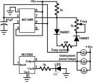 This circuit uses an MC3392 low side protected switch and an MC1455 timing circuit to form an automotive instrumentation panel lamp dimmer control. The brightness of incandescent lamps can be varied by Pulse Width Modulating the input of the MC3392....
[read more]
This circuit uses an MC3392 low side protected switch and an MC1455 timing circuit to form an automotive instrumentation panel lamp dimmer control. The brightness of incandescent lamps can be varied by Pulse Width Modulating the input of the MC3392....
[read more]
 This circuit is intended to let the user turn off a lamp by means of a switch placed far from bed, allowing him enough time to lie down before the lamp really switches off.
Obviously, users will be able to find different applications for this circuit in order to suit their needs....
[read more]
This circuit is intended to let the user turn off a lamp by means of a switch placed far from bed, allowing him enough time to lie down before the lamp really switches off.
Obviously, users will be able to find different applications for this circuit in order to suit their needs....
[read more]
 Here is a 12 volt / 2 amp lamp dimmer that can be used to dim a standard 25 watt automobile brake or backup bulb by controlling the duty cycle of a astable 555 timer oscillator. When the wiper of the potentiometer is at the uppermost position, the capacitor will charge quickly through both 1K resistors and the diode, producing a short positive interval and long negative interval which dims the lamp to near darkness....
[read more]
Here is a 12 volt / 2 amp lamp dimmer that can be used to dim a standard 25 watt automobile brake or backup bulb by controlling the duty cycle of a astable 555 timer oscillator. When the wiper of the potentiometer is at the uppermost position, the capacitor will charge quickly through both 1K resistors and the diode, producing a short positive interval and long negative interval which dims the lamp to near darkness....
[read more]
 In this circuit, a 120VAC lamp is slowly illuminated over a approximate 20 minute period. The bridge rectifier supplies 120 DC to the MOSFET and 60 watt lamp. A 6.2K, 5 watt resistor and zener diode is used to drop the voltage to 12 volts DC for the circuit power. The bridge rectifier should be rated at 200 volts and 5 amps or more. In operation, a 700 Hz triangle waveform is generated at pin 1 of the LM324 and a slow rising voltage is obtained at pin 8....
[read more]
In this circuit, a 120VAC lamp is slowly illuminated over a approximate 20 minute period. The bridge rectifier supplies 120 DC to the MOSFET and 60 watt lamp. A 6.2K, 5 watt resistor and zener diode is used to drop the voltage to 12 volts DC for the circuit power. The bridge rectifier should be rated at 200 volts and 5 amps or more. In operation, a 700 Hz triangle waveform is generated at pin 1 of the LM324 and a slow rising voltage is obtained at pin 8....
[read more]
 The sunset lamp comes on at full brightness and then slowly fades out over 1.5 hours time and stays off until power is recycled....
[read more]
The sunset lamp comes on at full brightness and then slowly fades out over 1.5 hours time and stays off until power is recycled....
[read more]
 The full wave phase control circuit below was found in a RCA power circuits book from 1969. The load is placed in series with the AC line and the four diodes provide a full wave rectified voltage to the anode of a SCR. Two small signal transistors are connected in a switch configuration so that when the voltage on the 2.2uF capacitor reaches about 8 volts, the transistors will switch on and discharge the capacitor through the SCR gate causing it to begin conducting....
[read more]
The full wave phase control circuit below was found in a RCA power circuits book from 1969. The load is placed in series with the AC line and the four diodes provide a full wave rectified voltage to the anode of a SCR. Two small signal transistors are connected in a switch configuration so that when the voltage on the 2.2uF capacitor reaches about 8 volts, the transistors will switch on and discharge the capacitor through the SCR gate causing it to begin conducting....
[read more]
 This circuit is similar to the "Fading Red Eyes" circuit (in the LED section) used to fade a pair of red LEDs. In this version, the lamps are faded by varying the duty cycle so that higher power incandescent lamps can be used without much power loss. The switching waveform is generated by comparing two linear ramps of different frequencies....
[read more]
This circuit is similar to the "Fading Red Eyes" circuit (in the LED section) used to fade a pair of red LEDs. In this version, the lamps are faded by varying the duty cycle so that higher power incandescent lamps can be used without much power loss. The switching waveform is generated by comparing two linear ramps of different frequencies....
[read more]
 This circuit is used to slowly illuminate and fade a pair of red
LEDs (light emitting diodes). The fading LEDs could be installed
as 'eyes' in a small pumpkin or skull as a Halloween attraction,
or mounted in a Christmas tree ornament. Or, they might be used
as a fancy power indicator for your computer, microwave oven,
stereo system, TV, or other appliance....
[read more]
This circuit is used to slowly illuminate and fade a pair of red
LEDs (light emitting diodes). The fading LEDs could be installed
as 'eyes' in a small pumpkin or skull as a Halloween attraction,
or mounted in a Christmas tree ornament. Or, they might be used
as a fancy power indicator for your computer, microwave oven,
stereo system, TV, or other appliance....
[read more]