Light flasher schematics
 The basic circuit illuminates up to ten LEDs in sequence, following the rhythm of music or speech picked-up by a small microphone. The expanded version can drive up to ten strips, formed by up to five LEDs each, at 9V supply. IC1A amplifies about 100 times the audio signal picked-up by the microphone and drives IC1B acting as peak-voltage detector. Its output peaks are synchronous with the peaks of the input signal and clock IC2, a ring decade counter capable of driving up to ten LEDs in sequence....
[read more]
The basic circuit illuminates up to ten LEDs in sequence, following the rhythm of music or speech picked-up by a small microphone. The expanded version can drive up to ten strips, formed by up to five LEDs each, at 9V supply. IC1A amplifies about 100 times the audio signal picked-up by the microphone and drives IC1B acting as peak-voltage detector. Its output peaks are synchronous with the peaks of the input signal and clock IC2, a ring decade counter capable of driving up to ten LEDs in sequence....
[read more]
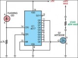
 This circuit adopts the rather unusual Bowes/White emitter coupled multivibrator circuit. The oscillation frequency is about 1Hz and is set by C1 value. The LED starts flashing when the photo resistor is scarcely illuminated. The onset of flashing can be set by trimming R2....
[read more]
This circuit adopts the rather unusual Bowes/White emitter coupled multivibrator circuit. The oscillation frequency is about 1Hz and is set by C1 value. The LED starts flashing when the photo resistor is scarcely illuminated. The onset of flashing can be set by trimming R2....
[read more]
 Here is the circuit diagram of Two Flashing LED's for different applications (such as model construction), and recreational. Having adjustable flashing speed with two potentiometers. It is the collection of a few active and passive components. This circuit is very easy to built ( a good idea for beginners ) and can be build on a general purpose pcb or on a veroboard. The complete picture and schematic of this project is shown below...
[read more]
Here is the circuit diagram of Two Flashing LED's for different applications (such as model construction), and recreational. Having adjustable flashing speed with two potentiometers. It is the collection of a few active and passive components. This circuit is very easy to built ( a good idea for beginners ) and can be build on a general purpose pcb or on a veroboard. The complete picture and schematic of this project is shown below...
[read more]
 Every self-respecting DIYer makes his own electronic dice with LEDs as spots. Then you don’t have to throw the dice anymore – just push the button. The electronics also ensures that nobody can try to improve his luck by fiddling with the dice. Too bad for sore losers! This circuit proves that an electronic die built using standard components can be made quite compact. The key component of here is a type 4060 digital counter (IC1)....
[read more]
Every self-respecting DIYer makes his own electronic dice with LEDs as spots. Then you don’t have to throw the dice anymore – just push the button. The electronics also ensures that nobody can try to improve his luck by fiddling with the dice. Too bad for sore losers! This circuit proves that an electronic die built using standard components can be made quite compact. The key component of here is a type 4060 digital counter (IC1)....
[read more]
 This circuit has been designed to provide a clearly visible light, formed by 13 high efficiency flashing LEDs arranged in a pseudo-rotating order. Due to low voltage, low drain battery operation and small size, the device is suitable for mounting on bicycles as a back light, or to put on by jogger/walkers. IC1 is a CMos version of the 555 IC wired as an astable multivibrator generating a 50% duty-cycle square wave at about 4Hz frequency....
[read more]
This circuit has been designed to provide a clearly visible light, formed by 13 high efficiency flashing LEDs arranged in a pseudo-rotating order. Due to low voltage, low drain battery operation and small size, the device is suitable for mounting on bicycles as a back light, or to put on by jogger/walkers. IC1 is a CMos version of the 555 IC wired as an astable multivibrator generating a 50% duty-cycle square wave at about 4Hz frequency....
[read more]
 This circuit is intended as a reliable replacement to thermally-activated switches used for Christmas tree lamp-flashing. The device formed by Q1, Q2 and related resistors triggers the SCR. Timing is provided by R1, R2 & C1. To change flashing frequency do not modify R1 and R2 values: set C1 value from 100 to 2200µF instead....
[read more]
This circuit is intended as a reliable replacement to thermally-activated switches used for Christmas tree lamp-flashing. The device formed by Q1, Q2 and related resistors triggers the SCR. Timing is provided by R1, R2 & C1. To change flashing frequency do not modify R1 and R2 values: set C1 value from 100 to 2200µF instead....
[read more]
 Ordinary LED flashers turn the LED on and off abruptly, which can get a little irritating after a while. The circuit shown here is more gentle on the eyes: the light intensity changes very slowly and sinusoidally, helping to generate a relaxed mood. The circuit shows a phase-shift oscillator with an adjustable current source at its output. The circuit is capable of driving two LEDs in series without affecting the current....
[read more]
Ordinary LED flashers turn the LED on and off abruptly, which can get a little irritating after a while. The circuit shown here is more gentle on the eyes: the light intensity changes very slowly and sinusoidally, helping to generate a relaxed mood. The circuit shows a phase-shift oscillator with an adjustable current source at its output. The circuit is capable of driving two LEDs in series without affecting the current....
[read more]
 Here is a portable, high-power incandescent electric lamp flasher. It is basically a dual flasher (alternating blinker) that can handle two separate 230V AC loads (bulbs L1 and L2). The circuit is fully transistorised and battery-powered. The free-running oscillator circuit is realised using two low-power, low-noise transistors T1 and T2. One of the two transistors is always conducting, while the other is blocking....
[read more]
Here is a portable, high-power incandescent electric lamp flasher. It is basically a dual flasher (alternating blinker) that can handle two separate 230V AC loads (bulbs L1 and L2). The circuit is fully transistorised and battery-powered. The free-running oscillator circuit is realised using two low-power, low-noise transistors T1 and T2. One of the two transistors is always conducting, while the other is blocking....
[read more]
 This novel circuit uses a flashing LED as the clock input for a 4017 decade counter. Typical flashing LEDs (eg, DSE cat Z-4044) flash at about 2Hz so the outputs Q0-Q9 will cycle through at that rate. For example, Q0 will turn on for half a second, then Q1, then Q2 etc up to Q8 then it will start at Q0 again. Up to nine outputs can be used. If you want fewer outputs, connect an earlier output to MR, pin 15. If MR is not used, connect it to 0V....
[read more]
This novel circuit uses a flashing LED as the clock input for a 4017 decade counter. Typical flashing LEDs (eg, DSE cat Z-4044) flash at about 2Hz so the outputs Q0-Q9 will cycle through at that rate. For example, Q0 will turn on for half a second, then Q1, then Q2 etc up to Q8 then it will start at Q0 again. Up to nine outputs can be used. If you want fewer outputs, connect an earlier output to MR, pin 15. If MR is not used, connect it to 0V....
[read more]
 This circuit was designed to provide that continuous light lamps already wired into a circuit, become flashing. Simply insert the circuit between existing lamp and negative supply. Especially suited for car or panel pilot lights, this device can drive lamps up to 10W....
[read more]
This circuit was designed to provide that continuous light lamps already wired into a circuit, become flashing. Simply insert the circuit between existing lamp and negative supply. Especially suited for car or panel pilot lights, this device can drive lamps up to 10W....
[read more]
 This circuit operates a LED in pulsing mode, i.e. the LED goes from off state, lights up gradually, then dims gradually, etc. This operation mode is obtained by a triangular wave generator formed by two op-amps contained in a very cheap 8 pin DIL case IC. Q1 ensures current buffering, in order to obtain a better load drive. R4 & C1 are the timing components: using the values shown in the parts list, the total period is about 4 seconds....
[read more]
This circuit operates a LED in pulsing mode, i.e. the LED goes from off state, lights up gradually, then dims gradually, etc. This operation mode is obtained by a triangular wave generator formed by two op-amps contained in a very cheap 8 pin DIL case IC. Q1 ensures current buffering, in order to obtain a better load drive. R4 & C1 are the timing components: using the values shown in the parts list, the total period is about 4 seconds....
[read more]
 This circuit was designed as a warning flasher to alert road users to dangerous situations in the dark. Alternatively, it can act as a bicycle light (subject to traffic regulations and legislation). White LEDs only are recommended if the circuit is used as a bicycle front light (i.e. for road illumination) and red LEDs only when used as a tail light. During the day, the two 1.6-V solar cells charge the two AA batteries. In darkness, the solar cell voltage disappears and the batteries automatically power the circuit. The flash frequency is about one per second and the LED on-time is about 330 ms....
[read more]
This circuit was designed as a warning flasher to alert road users to dangerous situations in the dark. Alternatively, it can act as a bicycle light (subject to traffic regulations and legislation). White LEDs only are recommended if the circuit is used as a bicycle front light (i.e. for road illumination) and red LEDs only when used as a tail light. During the day, the two 1.6-V solar cells charge the two AA batteries. In darkness, the solar cell voltage disappears and the batteries automatically power the circuit. The flash frequency is about one per second and the LED on-time is about 330 ms....
[read more]
 This circuit was purposely designed as a funny Halloween gadget. It should be placed to the rear of a badge or pin bearing a typical Halloween character image, e.g. a pumpkin, skull, black cat, witch, ghost etc. Two LEDs are fixed in place of the eyes of the character and will shine more or less brightly following the rhythm of the music or speech picked-up from surroundings by a small microphone. Two transistors provide the necessary amplification and drive the LEDs....
[read more]
This circuit was purposely designed as a funny Halloween gadget. It should be placed to the rear of a badge or pin bearing a typical Halloween character image, e.g. a pumpkin, skull, black cat, witch, ghost etc. Two LEDs are fixed in place of the eyes of the character and will shine more or less brightly following the rhythm of the music or speech picked-up from surroundings by a small microphone. Two transistors provide the necessary amplification and drive the LEDs....
[read more]
 This circuit operates two LED strips in pulsing mode, i.e. one LED strip goes from off state, lights up gradually, then dims gradually, etc. while the other LED strip does the contrary. Each strip can be made up from 2 to 5 LEDs at 9V supply. The two Op-Amps contained into IC1 form a triangular wave generator....
[read more]
This circuit operates two LED strips in pulsing mode, i.e. one LED strip goes from off state, lights up gradually, then dims gradually, etc. while the other LED strip does the contrary. Each strip can be made up from 2 to 5 LEDs at 9V supply. The two Op-Amps contained into IC1 form a triangular wave generator....
[read more]
 This circuit is similar to the LED clock using 12 neon indicator lamps instead of LEDs. It operates from 2 high capacity ni-cad cells (2.5 volts) which keep it going for a couple weeks. High voltage (70 volts) for the neon lamps is obtained from a small switching power supply using a 74HC14 Schmitt trigger squarewave oscillator, high voltage switching transistor, and 10 mH high Q inductor....
[read more]
This circuit is similar to the LED clock using 12 neon indicator lamps instead of LEDs. It operates from 2 high capacity ni-cad cells (2.5 volts) which keep it going for a couple weeks. High voltage (70 volts) for the neon lamps is obtained from a small switching power supply using a 74HC14 Schmitt trigger squarewave oscillator, high voltage switching transistor, and 10 mH high Q inductor....
[read more]
 This circuit has been designed to provide that continuous light lamps already wired into a circuit, become flashing. Simply insert the circuit between existing lamp and negative supply.
Especially suited for car or panel pilot lights, this device can drive lamps up to 10W....
[read more]
This circuit has been designed to provide that continuous light lamps already wired into a circuit, become flashing. Simply insert the circuit between existing lamp and negative supply.
Especially suited for car or panel pilot lights, this device can drive lamps up to 10W....
[read more]
 This circuit enables observation of movement between other stroboscopes. Generation of rectangular signal is based on NE555. This circuit requires a low power supply that is made from a simple transformer TR1, traditional rectifier bridge and zener diode....
[read more]
This circuit enables observation of movement between other stroboscopes. Generation of rectangular signal is based on NE555. This circuit requires a low power supply that is made from a simple transformer TR1, traditional rectifier bridge and zener diode....
[read more]
 This simple circuit drives 6 LEDs in 'Knightrider scanner mode'. Power consumption depends mainly on the type of LEDs used if you use a 7555 (555 CMOS version)....
[read more]
This simple circuit drives 6 LEDs in 'Knightrider scanner mode'. Power consumption depends mainly on the type of LEDs used if you use a 7555 (555 CMOS version)....
[read more]
 This one uses a much more powerful "horse shoe" Xenon tube which produces more light. You can also control the flash rate up to about 20Hz. Do not look directly at the flash tube when this thing is on!...
[read more]
This one uses a much more powerful "horse shoe" Xenon tube which produces more light. You can also control the flash rate up to about 20Hz. Do not look directly at the flash tube when this thing is on!...
[read more]
 This circuit operates a LED in pulsing mode, i.e. the LED goes from off state, lights up gradually, then dims gradually, etc....
[read more]
This circuit operates a LED in pulsing mode, i.e. the LED goes from off state, lights up gradually, then dims gradually, etc....
[read more]
 The purpose of this circuit was to create a ring in which LEDs or Lamps illuminate sequentially. Its main feature is a high versatility: you can build a loop containing any number of LEDs or Lamps, as each illuminating device has its own small circuit....
[read more]
The purpose of this circuit was to create a ring in which LEDs or Lamps illuminate sequentially. Its main feature is a high versatility: you can build a loop containing any number of LEDs or Lamps, as each illuminating device has its own small circuit....
[read more]
 Minimum parts counting
Designed for 3V battery operation...
[read more]
Minimum parts counting
Designed for 3V battery operation...
[read more]
 This schematic is version of a simple 10 LED chaser. There is no 555 timer used because at my local electronics store they are over $4 Cdn. Instead, an oscillator made up of two sections of a 4011 NAND gate is employed. This chip is very inexpensive and extremely common....
[read more]
This schematic is version of a simple 10 LED chaser. There is no 555 timer used because at my local electronics store they are over $4 Cdn. Instead, an oscillator made up of two sections of a 4011 NAND gate is employed. This chip is very inexpensive and extremely common....
[read more]
 The basic circuit illuminates up to ten LEDs in sequence, following the rhythm of music or speech picked-up by a small microphone. The expanded version can drive up to ten strips, formed by up to five LEDs each, at 9V supply....
[read more]
The basic circuit illuminates up to ten LEDs in sequence, following the rhythm of music or speech picked-up by a small microphone. The expanded version can drive up to ten strips, formed by up to five LEDs each, at 9V supply....
[read more]
 This circuit operates two LED strips in pulsing mode, i.e. one LED strip goes from off state, lights up gradually, then dims gradually, etc. while the other LED strip do the contrary....
[read more]
This circuit operates two LED strips in pulsing mode, i.e. one LED strip goes from off state, lights up gradually, then dims gradually, etc. while the other LED strip do the contrary....
[read more]
 Nite Rider Lights...
[read more]
Nite Rider Lights...
[read more]
 This circuit is intended as a reliable replacement to thermally-activated switches used for Christmas tree lamp-flashing....
[read more]
This circuit is intended as a reliable replacement to thermally-activated switches used for Christmas tree lamp-flashing....
[read more]
 In this circuit, one, two or three neon indicator bulbs can be made to flash in sequence at rates determined by the R and C values. In the single stage circuit, using one lamp, the capacitor charges through the resistor until the ionization potential of the neon is reached (about 70 volts) and then discharges quickly through the lamp until the voltage falls below what is needed to sustain the lamp which is approximately 45 volts....
[read more]
In this circuit, one, two or three neon indicator bulbs can be made to flash in sequence at rates determined by the R and C values. In the single stage circuit, using one lamp, the capacitor charges through the resistor until the ionization potential of the neon is reached (about 70 volts) and then discharges quickly through the lamp until the voltage falls below what is needed to sustain the lamp which is approximately 45 volts....
[read more]
 This circuit is basically the same as the 10 channel LED sequencer with the addition of solid state relays to control the AC lamps. The relay shown in the diagram is a Radio Shack 3 amp unit (part no. 275-310) that requires 1.2 volts DC to activate. No current spec was given but I assume it needs just a few milliamps to light the internal LED. A 360 ohm resistor is shown which would limit the current to 17 mA using a 9 volt supply....
[read more]
This circuit is basically the same as the 10 channel LED sequencer with the addition of solid state relays to control the AC lamps. The relay shown in the diagram is a Radio Shack 3 amp unit (part no. 275-310) that requires 1.2 volts DC to activate. No current spec was given but I assume it needs just a few milliamps to light the internal LED. A 360 ohm resistor is shown which would limit the current to 17 mA using a 9 volt supply....
[read more]
 The LED flasher circuits below operate on a single 1.5 volt battery. The circuit on the upper right uses the popular LM3909 LED flasher IC and requires only a timing capacitor and LED....
[read more]
The LED flasher circuits below operate on a single 1.5 volt battery. The circuit on the upper right uses the popular LM3909 LED flasher IC and requires only a timing capacitor and LED....
[read more]