Switches schematics
 The IR photo transistor Q1 (Radio Shack 276-145A) or similar is connected to the set input (pin 6). The photo transistor should be shielded from direct light so that the voltage at the set input (pin 6) is less than 1 volt under ambient conditions and moves to more than 10 volts when illuminated by the laser pointer or other light source...
[read more]
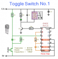
 The below uses a CMOS dual D flip flop (CD4013) to toggle a relay or other load with a momentary push button. Several push buttons can be wired in parallel to control the relay from multiple locations....
[read more]
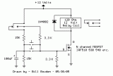
 In operation, when the relay is deactivated, the 100uF capacitor will charge to 6 volts. When the button is pressed, the capacitor will apply 6 volts to the MOSFET gate turning it on. The capacitor voltage (and gate voltage) will fall from 6 to 3 volts in about 200 mS which should be enough time for the relay contacts to move. For very slow relays, a larger capacitor may be needed....
[read more]
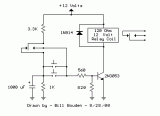
 The circuit requires a double pole, double throw relay in conjunction with a single transistor to allow toggling the relay with a momentary push button. One set of relay contacts is used to control the load, while the other is used to provide feedback to keep the relay activated or deactivated. Several push buttons can be wired in parallel to allow toggling the relay from different locations....
[read more]
 This toggle circuit operates by using a couple 555 timers wired as inverters. Pins 2 and 6 are the threshold and trigger inputs to the first timer and pin 5 is the output. The output at pin 5 will always be the inverse of the input at pins 2 and 6. Likewise, the output at pin 9 of the second timer will always be the inverse of the input at pins 8 and 12. A 100K resistor connects the output of one inverter to the input of the other so the state of one will be the opposite of the other....
[read more]
 This 555 timer circuit toggles a relay when a button is pressed. Pins 2 and 6, the threshold and trigger inputs, are held at 1/2 the supply voltage by the two 10K resistors. When the output is high, the capacitor charges through the 100K resistor, and discharges when the output is low. When the button is pressed, the capacitor voltage is applied to pins 2 and 6 which causes the output to change to the opposite state....
[read more]
 It is useful where the load needs to be switched on from one location and switched off from another. Any number of momentary (N/O) switches or push buttons can be connected in parallel....
[read more]
 This is a circuit for alternative sources selection. It combines mechanical selection using a rotating switch S1, the electronic drive of the relays RL 1-10 and also the optical indication of the selection by the Display DSP1....
[read more]
 The Elect. Sel. 8 is a simple circuit, with a choice of 8 sources of any sort ,of 8 independent switches. Each switch corresponding with a relay for example the switch S1 activates the RL1 e.t.c. The uses of the circuit are quite a few, choice of entrances in a sound amplifier, choice of command, in a digital circuit etc. In each entrance a LED which may be independent, except if switches with led are used....
[read more]
 This simple circuit will energize and de-energize a relay at the push of a button. Pushing the button once - will energize the relay. And pushing it a second time - will de-energize the relay. The accompanying Circuit Description offers a good introduction to the workings of the Cmos 4013....
[read more]
 A simple and convenient way to interface 2 relays for switching application in your project. This relay driver boosts the input impedance with a regular BC547 NPN transistor (or equivalent). Very common driver. It can drive a variety of relays, including a reed-relay. Transistor Q1and Q2 are a simple common-emitter amplifier that increases the effective sensitivity of the 12 volt relay coil about a 100 times, or in other words, the current gain for this circuit is 100. Using this setup reduces the relay sensitivity to a few volts. R3 and R4 restricts the input current to Q1 and Q2 to a safe limit. Diodes D3 and D4 are EMF dampers and filter off any sparking when the relay de-energizes....
[read more]
 Due to the low current drawing, the circuit can be supplied from 230Vac mains without a transformer. Supply voltage is reduced to 12Vdc by means of C1 reactance, a two diode rectifier cell D1 & D2 and Zener diode D3. IC1A, IC1B, R2, R3 and C3 form a reliable bounce-free toggle switch operated by P1. R4 and C4, wired to pin #6 of IC1B reset the circuit (lamp off) when power supply is applied. IC1C and IC1D wired in parallel act as a buffer, driving the Gate of the Triac through R5....
[read more]