General electronics schematics
![]() For a collector follower with emitter resistor, you’ll often find that the gain per stage is no more than 10 to 50 times. The gain increases when the emitter resistor is omitted. Unfortunately, the distortion also increases. With a ubiquitous transistor such as the BC547B, the gain of the transistor is roughly equal to 40 times the collector current (Ic), provided the collector current is less than a few milliamps. This value is in theory equal to the expression q/KT, where q is the charge of the electron, K is Boltzmann’s constant and T is the temperature in Kelvin....
[read more]
For a collector follower with emitter resistor, you’ll often find that the gain per stage is no more than 10 to 50 times. The gain increases when the emitter resistor is omitted. Unfortunately, the distortion also increases. With a ubiquitous transistor such as the BC547B, the gain of the transistor is roughly equal to 40 times the collector current (Ic), provided the collector current is less than a few milliamps. This value is in theory equal to the expression q/KT, where q is the charge of the electron, K is Boltzmann’s constant and T is the temperature in Kelvin....
[read more]
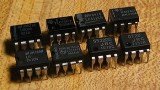 Typically the op-amp's very large gain is controlled by negative feedback, which largely determines the magnitude of its output ("closed-loop") voltage gain in amplifier applications, or the transfer function required (in analog computers). Without negative feedback, and perhaps with positive feedback for regeneration, an op-amp essentially acts as a comparator. High input impedance at the input terminals (ideally infinite) and low output impedance at the output terminal(s) (ideally zero) are important typical characteristics....
[read more]
Typically the op-amp's very large gain is controlled by negative feedback, which largely determines the magnitude of its output ("closed-loop") voltage gain in amplifier applications, or the transfer function required (in analog computers). Without negative feedback, and perhaps with positive feedback for regeneration, an op-amp essentially acts as a comparator. High input impedance at the input terminals (ideally infinite) and low output impedance at the output terminal(s) (ideally zero) are important typical characteristics....
[read more]
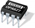 Although modern integrated circuit operational amplifiers ease linear circuit design, IC processing limits amplifier output power. Many applications, however, require substantially greater output voltage swing or current (or both) than IC amplifiers can deliver. In these situations an output “booster,” or post amplifier, is required to achieve the needed voltage or current gain. Normally, this stage is placed within the feedback loop of the operational amplifier so that the low drift and stable gain characteristics of the amplifier are retained....
[read more]
Although modern integrated circuit operational amplifiers ease linear circuit design, IC processing limits amplifier output power. Many applications, however, require substantially greater output voltage swing or current (or both) than IC amplifiers can deliver. In these situations an output “booster,” or post amplifier, is required to achieve the needed voltage or current gain. Normally, this stage is placed within the feedback loop of the operational amplifier so that the low drift and stable gain characteristics of the amplifier are retained....
[read more]
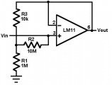 This circuit uses an LM11 to form a voltage follower with 1G ohm input resistance built using standard resistor values. With the input disconnected, the input offset voltage is multiplied by the same factor as R2; but the added error is small because the offset voltage of the LM11 is so low. When the input is connected to a source less than 1G ohm, this error is reduced. For an ac-coupled input a second 10M resistor could be connected in series with the inverting input to virtually eliminate bias current error; bypassing it would give minimal noise....
[read more]
This circuit uses an LM11 to form a voltage follower with 1G ohm input resistance built using standard resistor values. With the input disconnected, the input offset voltage is multiplied by the same factor as R2; but the added error is small because the offset voltage of the LM11 is so low. When the input is connected to a source less than 1G ohm, this error is reduced. For an ac-coupled input a second 10M resistor could be connected in series with the inverting input to virtually eliminate bias current error; bypassing it would give minimal noise....
[read more]
![]() Transistor / Diode / IC (DIP) Outlines...
[read more]
Transistor / Diode / IC (DIP) Outlines...
[read more]
 The op-amp is basically a differential amplifier having a large voltage gain, very high input impedance and low output impedance. The op-amp has a "inverting" or (-) input and "noninverting" or (+) input and a single output. The op-amp is usually powered by a dual polarity power supply in the range of +/- 5 volts to +/- 15 volts. A simple dual polarity power supply is shown in the figure below which can be assembled with two 9 volt batteries....
[read more]
The op-amp is basically a differential amplifier having a large voltage gain, very high input impedance and low output impedance. The op-amp has a "inverting" or (-) input and "noninverting" or (+) input and a single output. The op-amp is usually powered by a dual polarity power supply in the range of +/- 5 volts to +/- 15 volts. A simple dual polarity power supply is shown in the figure below which can be assembled with two 9 volt batteries....
[read more]