Timer schematics
 This timer was designed mainly to switch off a portable radio after some time: in this way, one can fall asleep on the sand or on a hammock, resting assured that the receiver will switch off automatically after some time, saving battery costs....
[read more]
This timer was designed mainly to switch off a portable radio after some time: in this way, one can fall asleep on the sand or on a hammock, resting assured that the receiver will switch off automatically after some time, saving battery costs....
[read more]
 This circuit was developed since a number of visitors of this website requested a timer capable of emitting a beep after one, two, three minutes and so on, for jogging purposes. As shown in the circuit diagram, SW1 is a 1 pole 9 ways Rotary Switch. Setting the switch in position 1, the Piezo sounder emits three short beeps every minute. In position 2 the same thing happens after a 2 minutes delay, and so on, reaching a maximum interval of 9 minutes in position 9....
[read more]
This circuit was developed since a number of visitors of this website requested a timer capable of emitting a beep after one, two, three minutes and so on, for jogging purposes. As shown in the circuit diagram, SW1 is a 1 pole 9 ways Rotary Switch. Setting the switch in position 1, the Piezo sounder emits three short beeps every minute. In position 2 the same thing happens after a 2 minutes delay, and so on, reaching a maximum interval of 9 minutes in position 9....
[read more]
 This circuit turns-off an amplifier or any other device when a low level audio signal fed to its input is absent for 15 minutes at least. Pushing P1 the device is switched-on feeding any appliance connected to SK1. Input audio signal is boosted and squared by IC2A & IC2B and monitored by LED D4. When D4 illuminates, albeit for a very short peak, IC3 is reset and restarts its counting....
[read more]
This circuit turns-off an amplifier or any other device when a low level audio signal fed to its input is absent for 15 minutes at least. Pushing P1 the device is switched-on feeding any appliance connected to SK1. Input audio signal is boosted and squared by IC2A & IC2B and monitored by LED D4. When D4 illuminates, albeit for a very short peak, IC3 is reset and restarts its counting....
[read more]
 This circuit is intended for alerting purposes after a certain time is elapsed. It is suitable for table games requiring a fixed time to answer a question, or to move a piece etc. In this view it is a modern substitute for the old sandglass. Useful also for time control when children are brushing teeth (at least two minutes!), or in the kitchen, and so on....
[read more]
This circuit is intended for alerting purposes after a certain time is elapsed. It is suitable for table games requiring a fixed time to answer a question, or to move a piece etc. In this view it is a modern substitute for the old sandglass. Useful also for time control when children are brushing teeth (at least two minutes!), or in the kitchen, and so on....
[read more]
 The purpose of this circuit is to power a lamp or other appliance for a given time (30 minutes in this case), and then to turn it off. It is useful when reading at bed by night, turning off the bedside lamp automatically in case the reader falls asleep... After turn-on by P1 pushbutton, the LED illuminates for around 25 minutes, but then it starts to blink for two minutes, stops blinking for two minutes and blinks for another two just before switching the lamp off, thus signaling that the on-time is ending. If the user want to prolong the reading, he/she can earn another half-hour of light by pushing on P1. Turning-off the lamp at user's ease is obtained by pushing on P2....
[read more]
The purpose of this circuit is to power a lamp or other appliance for a given time (30 minutes in this case), and then to turn it off. It is useful when reading at bed by night, turning off the bedside lamp automatically in case the reader falls asleep... After turn-on by P1 pushbutton, the LED illuminates for around 25 minutes, but then it starts to blink for two minutes, stops blinking for two minutes and blinks for another two just before switching the lamp off, thus signaling that the on-time is ending. If the user want to prolong the reading, he/she can earn another half-hour of light by pushing on P1. Turning-off the lamp at user's ease is obtained by pushing on P2....
[read more]
 Protect your home appliances from voltage spikes with this simple time delay circuit. Whenever power to the appliances is switched on or resumes after mains failure, the oscillator starts oscillating and D5 blinks. This continues for three minutes. After that, Q14 output of IC CD4060 goes high to trigger the gate of the SCR through D4. At this moment, the voltage is available at the cathode of the SCR, which energizes the relay coil to activate the appliance and D6 glows. Switch SW1 is used for quick start without waiting for delay....
[read more]
Protect your home appliances from voltage spikes with this simple time delay circuit. Whenever power to the appliances is switched on or resumes after mains failure, the oscillator starts oscillating and D5 blinks. This continues for three minutes. After that, Q14 output of IC CD4060 goes high to trigger the gate of the SCR through D4. At this moment, the voltage is available at the cathode of the SCR, which energizes the relay coil to activate the appliance and D6 glows. Switch SW1 is used for quick start without waiting for delay....
[read more]
 Most thefts happen after midnight hours when people enter the second phase of sleep called ‘paradoxical’ sleep. Here is an energy-saving circuit that causes the thieves to abort the theft attempt by lighting up the possible sites of intrusion (such as kitchen or backyard of your house) at around 1:00 am. It automatically resets in the morning. The circuit is fully automatic and uses a CMOS IC CD 4060 to get the desired time delay. Light-dependent resistor LDR1 controls reset pin 12 of IC1 for its automatic action. During day time, the low resistance of LDR1 makes pin 12 of IC1 ‘high,’ so it doesn’t oscillate....
[read more]
Most thefts happen after midnight hours when people enter the second phase of sleep called ‘paradoxical’ sleep. Here is an energy-saving circuit that causes the thieves to abort the theft attempt by lighting up the possible sites of intrusion (such as kitchen or backyard of your house) at around 1:00 am. It automatically resets in the morning. The circuit is fully automatic and uses a CMOS IC CD 4060 to get the desired time delay. Light-dependent resistor LDR1 controls reset pin 12 of IC1 for its automatic action. During day time, the low resistance of LDR1 makes pin 12 of IC1 ‘high,’ so it doesn’t oscillate....
[read more]
 The two circuits illustrate opening a relay contact a short time after the ignition or ligh switch is turned off. The capacitor is charged and the relay is closed when the voltage at the diode anode rises to +12 volts....
[read more]
The two circuits illustrate opening a relay contact a short time after the ignition or ligh switch is turned off. The capacitor is charged and the relay is closed when the voltage at the diode anode rises to +12 volts....
[read more]
 Here's a power-on time delay relay circuit that takes advantage of the emitter/base breakdown voltage of an ordinary bi-polar transistor. The reverse connected emitter/base junction of a 2N3904 transistor is used as an 8 volt zener diode which creates a higher turn-on voltage for the Darlington connected transistor pair....
[read more]
Here's a power-on time delay relay circuit that takes advantage of the emitter/base breakdown voltage of an ordinary bi-polar transistor. The reverse connected emitter/base junction of a 2N3904 transistor is used as an 8 volt zener diode which creates a higher turn-on voltage for the Darlington connected transistor pair....
[read more]
 The circuit illustrates generating a single positive pulse which is delayed relative to the trigger input time....
[read more]
The circuit illustrates generating a single positive pulse which is delayed relative to the trigger input time....
[read more]
 The two circuits illustrate using the 555 timer to close a relay for a predetermined amount of time by pressing a momentary N/O push button. The circuit on the left can be used for long time periods where the push button can be pressed and released before the end of the timing period. For shorter periods, a capacitor can be used to isolate the switch so that only the initial switch closure is seen by the timer input and the switch can remain closed for an unlimited period without effecting the output....
[read more]
The two circuits illustrate using the 555 timer to close a relay for a predetermined amount of time by pressing a momentary N/O push button. The circuit on the left can be used for long time periods where the push button can be pressed and released before the end of the timing period. For shorter periods, a capacitor can be used to isolate the switch so that only the initial switch closure is seen by the timer input and the switch can remain closed for an unlimited period without effecting the output....
[read more]
 A single Schmitt Trigger inverter stage (1/6 of 74HC14) is used as a squarewave oscillator to produce a low frequency of about 0.5 Hertz. The 10K resistor in series with the input (pin 1) reduces the capacitor discharge current through the inverter input internal protection diodes if the circuit is suddenly disconnected from the supply. This resistor may not be needed but is a good idea to use....
[read more]
A single Schmitt Trigger inverter stage (1/6 of 74HC14) is used as a squarewave oscillator to produce a low frequency of about 0.5 Hertz. The 10K resistor in series with the input (pin 1) reduces the capacitor discharge current through the inverter input internal protection diodes if the circuit is suddenly disconnected from the supply. This resistor may not be needed but is a good idea to use....
[read more]
 In this circuit a LM339 quad voltage comparator is used to generate a time delay and control a high current output at low voltage. Approximatey 5 amps of current can be obtained using a couple fresh alkaline D batteries. Three of the comparators are wired in parallel to drive a medium power PNP transistor (2N2905 or similar) which in turn drives a high current NPN transistor (TIP35 or similar)....
[read more]
In this circuit a LM339 quad voltage comparator is used to generate a time delay and control a high current output at low voltage. Approximatey 5 amps of current can be obtained using a couple fresh alkaline D batteries. Three of the comparators are wired in parallel to drive a medium power PNP transistor (2N2905 or similar) which in turn drives a high current NPN transistor (TIP35 or similar)....
[read more]
 This circuit provides a visual 9 second delay using a 7 segment digital readout LED. When the switch is closed, the CD4010 up/down counter is preset to 9 and the 555 timer is disabled with the output held high....
[read more]
This circuit provides a visual 9 second delay using a 7 segment digital readout LED. When the switch is closed, the CD4010 up/down counter is preset to 9 and the 555 timer is disabled with the output held high....
[read more]
 This circuit provides a visual 9 second delay using 10 LEDs before closing a 12 volt relay. When the reset switch is closed, the 4017 decade counter will be reset to the 0 count which illuminates the LED driven from pin 3. The 555 timer output at pin 3 will be high and the voltage at pins 6 and 2 of the timer will be a little less than the lower trigger point, or about 3 volts....
[read more]
This circuit provides a visual 9 second delay using 10 LEDs before closing a 12 volt relay. When the reset switch is closed, the 4017 decade counter will be reset to the 0 count which illuminates the LED driven from pin 3. The 555 timer output at pin 3 will be high and the voltage at pins 6 and 2 of the timer will be a little less than the lower trigger point, or about 3 volts....
[read more]
 This is a combination digital clock timer and solar panel charge controller used to maintain a deep cycle battery from a solar panel. The timer output is used to control a 12 volt load for a 32 minute time interval each day....
[read more]
This is a combination digital clock timer and solar panel charge controller used to maintain a deep cycle battery from a solar panel. The timer output is used to control a 12 volt load for a 32 minute time interval each day....
[read more]
 In the circuit, 60 individual LEDs are used to indicate the minutes of a clock and 12 LEDs indicate hours. The power supply and time base circuitry is the same as described in the 28 LED clock circuit above. The minutes section of the clock is comprised of eight 74HCT164 shift registers cascaded so that a single bit can be recirculated through the 60 stages indicating the appropriate minute of the hour....
[read more]
In the circuit, 60 individual LEDs are used to indicate the minutes of a clock and 12 LEDs indicate hours. The power supply and time base circuitry is the same as described in the 28 LED clock circuit above. The minutes section of the clock is comprised of eight 74HCT164 shift registers cascaded so that a single bit can be recirculated through the 60 stages indicating the appropriate minute of the hour....
[read more]
 This is a programmable clock timer circuit that uses individual LEDs to indicate hours and minutes. 12 LEDs can be arranged in a circle to represent the 12 hours of a clock face and an additional 12 LEDs can be arranged in an outer circle to indicate 5 minute intervals within the hour. 4 additional LEDs are used to indicate 1 to 4 minutes of time within each 5 minute interval....
[read more]
This is a programmable clock timer circuit that uses individual LEDs to indicate hours and minutes. 12 LEDs can be arranged in a circle to represent the 12 hours of a clock face and an additional 12 LEDs can be arranged in an outer circle to indicate 5 minute intervals within the hour. 4 additional LEDs are used to indicate 1 to 4 minutes of time within each 5 minute interval....
[read more]
 A small circuit that can find a lot applications of measurement time....
[read more]
A small circuit that can find a lot applications of measurement time....
[read more]
 A wide range auto turn OFF timer covering 1 minute to 20 hours in three ranges...
[read more]
A wide range auto turn OFF timer covering 1 minute to 20 hours in three ranges...
[read more]
 Relay Timer switch...
[read more]
Relay Timer switch...
[read more]
 This circuit is the opposite of Repeating Timer No.5. It will only begin to operate if the temperature falls below the preset level. Again - the variable resistor (preset) lets you choose the temperature below which the timer will function....
[read more]
This circuit is the opposite of Repeating Timer No.5. It will only begin to operate if the temperature falls below the preset level. Again - the variable resistor (preset) lets you choose the temperature below which the timer will function....
[read more]
 This circuit is a temperature controlled version of Repeating Timer No.3 . The light dependent resistor has been replaced by a temperature dependent resistor or thermistor. And a small preset potentiometer lets you choose the temperature above which the timer will operate....
[read more]
This circuit is a temperature controlled version of Repeating Timer No.3 . The light dependent resistor has been replaced by a temperature dependent resistor or thermistor. And a small preset potentiometer lets you choose the temperature above which the timer will operate....
[read more]
 This circuit is the opposite of Repeating Timer No.3 . Its operation can be limited to the hours of darkness. Again - the variable resistor (preset) lets you choose the level of darkness at which the timer will begin to function....
[read more]
This circuit is the opposite of Repeating Timer No.3 . Its operation can be limited to the hours of darkness. Again - the variable resistor (preset) lets you choose the level of darkness at which the timer will begin to function....
[read more]
 This circuit is very similar to Repeating Interval Timer No.2 . However - the addition of a light dependent resistor means that the operation of this timer can be limited to the daylight hours. A variable resistor (preset) lets you choose the level of darkness at which the timer will cease to function....
[read more]
This circuit is very similar to Repeating Interval Timer No.2 . However - the addition of a light dependent resistor means that the operation of this timer can be limited to the daylight hours. A variable resistor (preset) lets you choose the level of darkness at which the timer will cease to function....
[read more]
 This is a simpler repeating timer circuit. It uses just one Cmos IC - wired as an asymmetric oscillator. The length of time the relay remains energized - and the length of time it remains de-energized - are set independently....
[read more]
This is a simpler repeating timer circuit. It uses just one Cmos IC - wired as an asymmetric oscillator. The length of time the relay remains energized - and the length of time it remains de-energized - are set independently....
[read more]
 This circuit has an adjustable output timer that will re-trigger at regular intervals. The output period can be anything from a fraction of a second to half-an-hour or more - and it can be made to recur at regular intervals of anything from seconds to days and beyond....
[read more]
This circuit has an adjustable output timer that will re-trigger at regular intervals. The output period can be anything from a fraction of a second to half-an-hour or more - and it can be made to recur at regular intervals of anything from seconds to days and beyond....
[read more]
 A pair of multi-range timers offering periods of up to 24 hours and beyond. Both are essentially the same. The main difference is, that when the time runs out, Version 1 energizes the relay and Version 2 de-energizes it. The first uses less power while the timer is running; and the second uses less power after the timer stops. Pick the one that best suits your application....
[read more]
A pair of multi-range timers offering periods of up to 24 hours and beyond. Both are essentially the same. The main difference is, that when the time runs out, Version 1 energizes the relay and Version 2 de-energizes it. The first uses less power while the timer is running; and the second uses less power after the timer stops. Pick the one that best suits your application....
[read more]
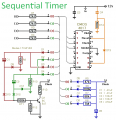 This timer will provide a sequence of up to ten separate events. The length of each event is set independently. And the sequence will run a fixed number of times - or repeat continuosly. The individual events within the sequence - can be made to repeat and/or overlap. The accompanying Support Material includes a detailed description of how the Cmos 4017 works....
[read more]
This timer will provide a sequence of up to ten separate events. The length of each event is set independently. And the sequence will run a fixed number of times - or repeat continuosly. The individual events within the sequence - can be made to repeat and/or overlap. The accompanying Support Material includes a detailed description of how the Cmos 4017 works....
[read more]
 This timer was designed for people wanting to get tanned but at the same time wishing to avoid an excessive exposure to sunlight. A Rotary Switch sets the timer according to six classified Photo-types (see table). A Photo resistor extends the preset time value according to sunlight brightness (see table). When preset time ends, the beeper emits an intermittent signal and, to stop it, a complete switch-off of the circuit via SW2 is necessary....
[read more]
This timer was designed for people wanting to get tanned but at the same time wishing to avoid an excessive exposure to sunlight. A Rotary Switch sets the timer according to six classified Photo-types (see table). A Photo resistor extends the preset time value according to sunlight brightness (see table). When preset time ends, the beeper emits an intermittent signal and, to stop it, a complete switch-off of the circuit via SW2 is necessary....
[read more]