LED and light schematics
 This circuit is usable as a Night Lamp when a wall mains socket is not available to plug-in an ever running small neon lamp device. In order to ensure minimum battery consumption, one 1.5V cell is used and simple voltage doublers drives a pulsating ultra-bright LED: current drawing is less than 500µA. An optional Photo resistor will switch-off the circuit in daylight or when room lamps illuminate, allowing further current economy. This device will run for about 3 months continuously on an ordinary AA sized cell or for around 6 months on an alkaline type cell but, adding the Photo resistor circuitry, running time will be doubled or, very likely, triplicates. IC1 generates a square wave at about 4 Hz frequencies. C2 & D2 form voltage doublers, necessary to raise the battery voltage to a peak value able to drive the LED....
[read more]
This circuit is usable as a Night Lamp when a wall mains socket is not available to plug-in an ever running small neon lamp device. In order to ensure minimum battery consumption, one 1.5V cell is used and simple voltage doublers drives a pulsating ultra-bright LED: current drawing is less than 500µA. An optional Photo resistor will switch-off the circuit in daylight or when room lamps illuminate, allowing further current economy. This device will run for about 3 months continuously on an ordinary AA sized cell or for around 6 months on an alkaline type cell but, adding the Photo resistor circuitry, running time will be doubled or, very likely, triplicates. IC1 generates a square wave at about 4 Hz frequencies. C2 & D2 form voltage doublers, necessary to raise the battery voltage to a peak value able to drive the LED....
[read more]
 The basic circuit illuminates up to ten LEDs in sequence, following the rhythm of music or speech picked-up by a small microphone. The expanded version can drive up to ten strips, formed by up to five LEDs each, at 9V supply. IC1A amplifies about 100 times the audio signal picked-up by the microphone and drives IC1B acting as peak-voltage detector. Its output peaks are synchronous with the peaks of the input signal and clock IC2, a ring decade counter capable of driving up to ten LEDs in sequence....
[read more]
The basic circuit illuminates up to ten LEDs in sequence, following the rhythm of music or speech picked-up by a small microphone. The expanded version can drive up to ten strips, formed by up to five LEDs each, at 9V supply. IC1A amplifies about 100 times the audio signal picked-up by the microphone and drives IC1B acting as peak-voltage detector. Its output peaks are synchronous with the peaks of the input signal and clock IC2, a ring decade counter capable of driving up to ten LEDs in sequence....
[read more]
 This circuit is intended to let the user turn off a lamp by means of a switch placed far from bed, allowing him enough time to lie down before the lamp really switches off....
[read more]
This circuit is intended to let the user turn off a lamp by means of a switch placed far from bed, allowing him enough time to lie down before the lamp really switches off....
[read more]
 This device was designed on request; to control the light intensity of four filament lamps (i.e. a ring illuminator) powered by two AA or AAA batteries, for close-up pictures with a digital camera. Obviously it can be used in other ways, at anyone's will.IC1 generates a 150Hz square wave having a variable duty-cycle. When the cursor of P1 is fully rotated towards D1, the output positive pulses appearing at pin 3 of IC1 are very narrow....
[read more]
This device was designed on request; to control the light intensity of four filament lamps (i.e. a ring illuminator) powered by two AA or AAA batteries, for close-up pictures with a digital camera. Obviously it can be used in other ways, at anyone's will.IC1 generates a 150Hz square wave having a variable duty-cycle. When the cursor of P1 is fully rotated towards D1, the output positive pulses appearing at pin 3 of IC1 are very narrow....
[read more]
 This circuit adopts the rather unusual Bowes/White emitter coupled multivibrator circuit. The oscillation frequency is about 1Hz and is set by C1 value. The LED starts flashing when the photo resistor is scarcely illuminated. The onset of flashing can be set by trimming R2....
[read more]
This circuit adopts the rather unusual Bowes/White emitter coupled multivibrator circuit. The oscillation frequency is about 1Hz and is set by C1 value. The LED starts flashing when the photo resistor is scarcely illuminated. The onset of flashing can be set by trimming R2....
[read more]
 Here is the circuit diagram of IC Controlled Emergancy Light With Charger or simply 12V to 220V AC inverter circuit. The circuit shown here is that of the IC controlled emergency light. Its main features are: automatic switching-on of the light on mains failure and battery charger with over-charge protection. When mains is absent, relay RL2 is in de-energized state, feeding battery supply to inverter section via its N/C contacts and switch S1....
[read more]
Here is the circuit diagram of IC Controlled Emergancy Light With Charger or simply 12V to 220V AC inverter circuit. The circuit shown here is that of the IC controlled emergency light. Its main features are: automatic switching-on of the light on mains failure and battery charger with over-charge protection. When mains is absent, relay RL2 is in de-energized state, feeding battery supply to inverter section via its N/C contacts and switch S1....
[read more]
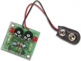 Here is the circuit diagram of Two Flashing LED's for different applications (such as model construction), and recreational. Having adjustable flashing speed with two potentiometers. It is the collection of a few active and passive components. This circuit is very easy to built ( a good idea for beginners ) and can be build on a general purpose pcb or on a veroboard. The complete picture and schematic of this project is shown below...
[read more]
Here is the circuit diagram of Two Flashing LED's for different applications (such as model construction), and recreational. Having adjustable flashing speed with two potentiometers. It is the collection of a few active and passive components. This circuit is very easy to built ( a good idea for beginners ) and can be build on a general purpose pcb or on a veroboard. The complete picture and schematic of this project is shown below...
[read more]
 Every self-respecting DIYer makes his own electronic dice with LEDs as spots. Then you don’t have to throw the dice anymore – just push the button. The electronics also ensures that nobody can try to improve his luck by fiddling with the dice. Too bad for sore losers! This circuit proves that an electronic die built using standard components can be made quite compact. The key component of here is a type 4060 digital counter (IC1)....
[read more]
Every self-respecting DIYer makes his own electronic dice with LEDs as spots. Then you don’t have to throw the dice anymore – just push the button. The electronics also ensures that nobody can try to improve his luck by fiddling with the dice. Too bad for sore losers! This circuit proves that an electronic die built using standard components can be made quite compact. The key component of here is a type 4060 digital counter (IC1)....
[read more]
 This circuit has been designed to provide a clearly visible light, formed by 13 high efficiency flashing LEDs arranged in a pseudo-rotating order. Due to low voltage, low drain battery operation and small size, the device is suitable for mounting on bicycles as a back light, or to put on by jogger/walkers. IC1 is a CMos version of the 555 IC wired as an astable multivibrator generating a 50% duty-cycle square wave at about 4Hz frequency....
[read more]
This circuit has been designed to provide a clearly visible light, formed by 13 high efficiency flashing LEDs arranged in a pseudo-rotating order. Due to low voltage, low drain battery operation and small size, the device is suitable for mounting on bicycles as a back light, or to put on by jogger/walkers. IC1 is a CMos version of the 555 IC wired as an astable multivibrator generating a 50% duty-cycle square wave at about 4Hz frequency....
[read more]
 A dimmer is quite unusual in a caravan or on a boat. Here we describe how you can make one. So if you would like to be able to adjust the mood when you’re entertaining friends and acquaintances, then this circuit enables you to do so. Designing a dimmer for 12 V is tricky business. The dimmers you find in your home are designed to operate from an AC voltage and use this AC voltage as a fundamental characteristic for their operation. Because we now have to start with 12 V DC, we have to generate the AC voltage ourselves....
[read more]
A dimmer is quite unusual in a caravan or on a boat. Here we describe how you can make one. So if you would like to be able to adjust the mood when you’re entertaining friends and acquaintances, then this circuit enables you to do so. Designing a dimmer for 12 V is tricky business. The dimmers you find in your home are designed to operate from an AC voltage and use this AC voltage as a fundamental characteristic for their operation. Because we now have to start with 12 V DC, we have to generate the AC voltage ourselves....
[read more]
 This circuit is intended as a reliable replacement to thermally-activated switches used for Christmas tree lamp-flashing. The device formed by Q1, Q2 and related resistors triggers the SCR. Timing is provided by R1, R2 & C1. To change flashing frequency do not modify R1 and R2 values: set C1 value from 100 to 2200µF instead....
[read more]
This circuit is intended as a reliable replacement to thermally-activated switches used for Christmas tree lamp-flashing. The device formed by Q1, Q2 and related resistors triggers the SCR. Timing is provided by R1, R2 & C1. To change flashing frequency do not modify R1 and R2 values: set C1 value from 100 to 2200µF instead....
[read more]
 This ultra-bright white LED lamp works on 230V AC with minimal power consumption. It can be used to illuminate VU meters, SWR meters, etc. Ultra-bright LEDs available in the market cost Rs 8 to 15. These LEDs emit a 1000-6000mCd bright white light like welding arc and work on 3 volts, 10 mA. Their maximum voltage is 3.6 volts and the current is 25 mA. Anti-static precautions should be taken when handling the LEDs....
[read more]
This ultra-bright white LED lamp works on 230V AC with minimal power consumption. It can be used to illuminate VU meters, SWR meters, etc. Ultra-bright LEDs available in the market cost Rs 8 to 15. These LEDs emit a 1000-6000mCd bright white light like welding arc and work on 3 volts, 10 mA. Their maximum voltage is 3.6 volts and the current is 25 mA. Anti-static precautions should be taken when handling the LEDs....
[read more]
 This circuit is designed on request and can be useful to those whishing to have, say, a red LED illuminated when an appliance is on and a green LED illuminated when the same appliance is off. Any mains operated appliance can be monitored by this circuit provided a suitable mains switch, capable of withstanding the full load current, is used for SW1.When SW1 is closed, the load and D4 are energized, Q1 is saturated and shorts D3, thus preventing its illumination....
[read more]
This circuit is designed on request and can be useful to those whishing to have, say, a red LED illuminated when an appliance is on and a green LED illuminated when the same appliance is off. Any mains operated appliance can be monitored by this circuit provided a suitable mains switch, capable of withstanding the full load current, is used for SW1.When SW1 is closed, the load and D4 are energized, Q1 is saturated and shorts D3, thus preventing its illumination....
[read more]
 The PR4403 is an enhanced cousin of the PR4402 40mA LED driver. It has an extra input called LS which can be taken low to turn the LED on. This makes it very easy to build an automatic LED lamp using a rechargeable battery and a solar module. The LS input is connected directly to the solar cell, which allows the module to be used as a light sensor at the same time as it charges the battery via a diode. When darkness falls so does the voltage across the solar module: when it is below a threshold value the PR4403 switches on. During the day the battery is charged and, with the LED of, the driver only draws 100µA....
[read more]
The PR4403 is an enhanced cousin of the PR4402 40mA LED driver. It has an extra input called LS which can be taken low to turn the LED on. This makes it very easy to build an automatic LED lamp using a rechargeable battery and a solar module. The LS input is connected directly to the solar cell, which allows the module to be used as a light sensor at the same time as it charges the battery via a diode. When darkness falls so does the voltage across the solar module: when it is below a threshold value the PR4403 switches on. During the day the battery is charged and, with the LED of, the driver only draws 100µA....
[read more]
 Ordinary LED flashers turn the LED on and off abruptly, which can get a little irritating after a while. The circuit shown here is more gentle on the eyes: the light intensity changes very slowly and sinusoidally, helping to generate a relaxed mood. The circuit shows a phase-shift oscillator with an adjustable current source at its output. The circuit is capable of driving two LEDs in series without affecting the current....
[read more]
Ordinary LED flashers turn the LED on and off abruptly, which can get a little irritating after a while. The circuit shown here is more gentle on the eyes: the light intensity changes very slowly and sinusoidally, helping to generate a relaxed mood. The circuit shows a phase-shift oscillator with an adjustable current source at its output. The circuit is capable of driving two LEDs in series without affecting the current....
[read more]
 Here is a portable, high-power incandescent electric lamp flasher. It is basically a dual flasher (alternating blinker) that can handle two separate 230V AC loads (bulbs L1 and L2). The circuit is fully transistorised and battery-powered. The free-running oscillator circuit is realised using two low-power, low-noise transistors T1 and T2. One of the two transistors is always conducting, while the other is blocking....
[read more]
Here is a portable, high-power incandescent electric lamp flasher. It is basically a dual flasher (alternating blinker) that can handle two separate 230V AC loads (bulbs L1 and L2). The circuit is fully transistorised and battery-powered. The free-running oscillator circuit is realised using two low-power, low-noise transistors T1 and T2. One of the two transistors is always conducting, while the other is blocking....
[read more]
 This novel circuit uses a flashing LED as the clock input for a 4017 decade counter. Typical flashing LEDs (eg, DSE cat Z-4044) flash at about 2Hz so the outputs Q0-Q9 will cycle through at that rate. For example, Q0 will turn on for half a second, then Q1, then Q2 etc up to Q8 then it will start at Q0 again. Up to nine outputs can be used. If you want fewer outputs, connect an earlier output to MR, pin 15. If MR is not used, connect it to 0V....
[read more]
This novel circuit uses a flashing LED as the clock input for a 4017 decade counter. Typical flashing LEDs (eg, DSE cat Z-4044) flash at about 2Hz so the outputs Q0-Q9 will cycle through at that rate. For example, Q0 will turn on for half a second, then Q1, then Q2 etc up to Q8 then it will start at Q0 again. Up to nine outputs can be used. If you want fewer outputs, connect an earlier output to MR, pin 15. If MR is not used, connect it to 0V....
[read more]
 Most PC enclosures provide only a single LED to indicate hard disk access, with the LED being connected to the motherboard via a two-pin connector. However, this LED only works with IDE drives, and if a SCSI disk controller is fitted, its activity will not be visibly noticeable. This small circuit remedies that problem using a multicolour LED. The activity LED for the IDE interface is usually driven by a connected device via one or more open-collector stages....
[read more]
Most PC enclosures provide only a single LED to indicate hard disk access, with the LED being connected to the motherboard via a two-pin connector. However, this LED only works with IDE drives, and if a SCSI disk controller is fitted, its activity will not be visibly noticeable. This small circuit remedies that problem using a multicolour LED. The activity LED for the IDE interface is usually driven by a connected device via one or more open-collector stages....
[read more]
 Here is a simple and powerful LED circuit that can be operated directly from the AC 100 volt to AC 230 Volts mains supply. The circuit can be used as mains power locator or night lamp etc.. The resistor R1,R2 and capacitor C1 provides necessary current limiting. The circuit is sufficiently immune against voltage spikes and surges....
[read more]
Here is a simple and powerful LED circuit that can be operated directly from the AC 100 volt to AC 230 Volts mains supply. The circuit can be used as mains power locator or night lamp etc.. The resistor R1,R2 and capacitor C1 provides necessary current limiting. The circuit is sufficiently immune against voltage spikes and surges....
[read more]
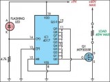
 This circuit was designed to provide that continuous light lamps already wired into a circuit, become flashing. Simply insert the circuit between existing lamp and negative supply. Especially suited for car or panel pilot lights, this device can drive lamps up to 10W....
[read more]
This circuit was designed to provide that continuous light lamps already wired into a circuit, become flashing. Simply insert the circuit between existing lamp and negative supply. Especially suited for car or panel pilot lights, this device can drive lamps up to 10W....
[read more]
 This circuit operates a LED in pulsing mode, i.e. the LED goes from off state, lights up gradually, then dims gradually, etc. This operation mode is obtained by a triangular wave generator formed by two op-amps contained in a very cheap 8 pin DIL case IC. Q1 ensures current buffering, in order to obtain a better load drive. R4 & C1 are the timing components: using the values shown in the parts list, the total period is about 4 seconds....
[read more]
This circuit operates a LED in pulsing mode, i.e. the LED goes from off state, lights up gradually, then dims gradually, etc. This operation mode is obtained by a triangular wave generator formed by two op-amps contained in a very cheap 8 pin DIL case IC. Q1 ensures current buffering, in order to obtain a better load drive. R4 & C1 are the timing components: using the values shown in the parts list, the total period is about 4 seconds....
[read more]
 This circuit was designed as a warning flasher to alert road users to dangerous situations in the dark. Alternatively, it can act as a bicycle light (subject to traffic regulations and legislation). White LEDs only are recommended if the circuit is used as a bicycle front light (i.e. for road illumination) and red LEDs only when used as a tail light. During the day, the two 1.6-V solar cells charge the two AA batteries. In darkness, the solar cell voltage disappears and the batteries automatically power the circuit. The flash frequency is about one per second and the LED on-time is about 330 ms....
[read more]
This circuit was designed as a warning flasher to alert road users to dangerous situations in the dark. Alternatively, it can act as a bicycle light (subject to traffic regulations and legislation). White LEDs only are recommended if the circuit is used as a bicycle front light (i.e. for road illumination) and red LEDs only when used as a tail light. During the day, the two 1.6-V solar cells charge the two AA batteries. In darkness, the solar cell voltage disappears and the batteries automatically power the circuit. The flash frequency is about one per second and the LED on-time is about 330 ms....
[read more]
 This circuit was purposely designed as a funny Halloween gadget. It should be placed to the rear of a badge or pin bearing a typical Halloween character image, e.g. a pumpkin, skull, black cat, witch, ghost etc. Two LEDs are fixed in place of the eyes of the character and will shine more or less brightly following the rhythm of the music or speech picked-up from surroundings by a small microphone. Two transistors provide the necessary amplification and drive the LEDs....
[read more]
This circuit was purposely designed as a funny Halloween gadget. It should be placed to the rear of a badge or pin bearing a typical Halloween character image, e.g. a pumpkin, skull, black cat, witch, ghost etc. Two LEDs are fixed in place of the eyes of the character and will shine more or less brightly following the rhythm of the music or speech picked-up from surroundings by a small microphone. Two transistors provide the necessary amplification and drive the LEDs....
[read more]
 This circuit operates two LED strips in pulsing mode, i.e. one LED strip goes from off state, lights up gradually, then dims gradually, etc. while the other LED strip does the contrary. Each strip can be made up from 2 to 5 LEDs at 9V supply. The two Op-Amps contained into IC1 form a triangular wave generator....
[read more]
This circuit operates two LED strips in pulsing mode, i.e. one LED strip goes from off state, lights up gradually, then dims gradually, etc. while the other LED strip does the contrary. Each strip can be made up from 2 to 5 LEDs at 9V supply. The two Op-Amps contained into IC1 form a triangular wave generator....
[read more]
 Here is a white-LED-based emergency light that offers the following advantages. 1-It is highly bright due to the use of white LEDs. 2-The light turns on automatically when mains supply fails, and turns off when mains power resumes. 3-It has its own battery charger. When the battery is fully charged, charging stops automatically. The charger power supply section is built around 3-terminal adjustable regulator IC LM317 (IC1), while the LED driver section is built around transistor BD140 (Q2)....
[read more]
Here is a white-LED-based emergency light that offers the following advantages. 1-It is highly bright due to the use of white LEDs. 2-The light turns on automatically when mains supply fails, and turns off when mains power resumes. 3-It has its own battery charger. When the battery is fully charged, charging stops automatically. The charger power supply section is built around 3-terminal adjustable regulator IC LM317 (IC1), while the LED driver section is built around transistor BD140 (Q2)....
[read more]
 This circuit is similar to the LED clock using 12 neon indicator lamps instead of LEDs. It operates from 2 high capacity ni-cad cells (2.5 volts) which keep it going for a couple weeks. High voltage (70 volts) for the neon lamps is obtained from a small switching power supply using a 74HC14 Schmitt trigger squarewave oscillator, high voltage switching transistor, and 10 mH high Q inductor....
[read more]
This circuit is similar to the LED clock using 12 neon indicator lamps instead of LEDs. It operates from 2 high capacity ni-cad cells (2.5 volts) which keep it going for a couple weeks. High voltage (70 volts) for the neon lamps is obtained from a small switching power supply using a 74HC14 Schmitt trigger squarewave oscillator, high voltage switching transistor, and 10 mH high Q inductor....
[read more]
 This circuit has been designed to provide that continuous light lamps already wired into a circuit, become flashing. Simply insert the circuit between existing lamp and negative supply.
Especially suited for car or panel pilot lights, this device can drive lamps up to 10W....
[read more]
This circuit has been designed to provide that continuous light lamps already wired into a circuit, become flashing. Simply insert the circuit between existing lamp and negative supply.
Especially suited for car or panel pilot lights, this device can drive lamps up to 10W....
[read more]
 This circuit enables observation of movement between other stroboscopes. Generation of rectangular signal is based on NE555. This circuit requires a low power supply that is made from a simple transformer TR1, traditional rectifier bridge and zener diode....
[read more]
This circuit enables observation of movement between other stroboscopes. Generation of rectangular signal is based on NE555. This circuit requires a low power supply that is made from a simple transformer TR1, traditional rectifier bridge and zener diode....
[read more]
 This little circuit can be used to dim lights up to about 350 watts. It uses a simple, standard TRIAC circuit that, in my expirience, generates very little heat. Please note that this circuit cannot be used with fluorescent lights....
[read more]
This little circuit can be used to dim lights up to about 350 watts. It uses a simple, standard TRIAC circuit that, in my expirience, generates very little heat. Please note that this circuit cannot be used with fluorescent lights....
[read more]
 This simple circuit drives 6 LEDs in 'Knightrider scanner mode'. Power consumption depends mainly on the type of LEDs used if you use a 7555 (555 CMOS version)....
[read more]
This simple circuit drives 6 LEDs in 'Knightrider scanner mode'. Power consumption depends mainly on the type of LEDs used if you use a 7555 (555 CMOS version)....
[read more]