Tools and measuring schematics
 This little circuit indicates the basic integrity of a printed board, detecting 0V, positive supply voltage from less than 3V to 30V and floating parts. If the probe is floating, as it would be in a broken track, then both LEDs barely light up, since there is no current to drive the transistors, but if the probe touches 0V or a positive voltage one or other lights. A digital signal should light them in proportion to the mark-space ratio whereas the output of a circuit oscillating at a frequency rate below about 20Hz will cause the LEDs to flicker alternatively. The LEDs will illuminate always at a constant intensity, no matter the voltage supply used, because they are fed by a very simple FET constant-current generator (Q1)....
[read more]
 Although it does not have the same charm as real mercury barometers with long glass tubes on pieces of carved and polished wood, the Torricelli barometer discussed here is a functional equivalent and electronic replica of the Torricelli barometer. Actually, rather than displaying the atmospheric pressure on the traditional digital displays, we preferred to reproduce the general look of this respected predecessor of electronic barometers....
[read more]
 Short circuits or broken pcb tracks can be easily recognized by means of a Multimeter, but this tool can give wrong results when testing the efficiency of a transistor or diode, unless the device under test is unsoldered and removed from the pcb. A further shortcoming affecting such way of testing is the necessity to keep firmly the probes on the pins of the device under test and at the same time to turn the head continually to read the Multimeter display....
[read more]
 This simple logic probe has both LEDs on with no signal at the input but due to the nor gates connected to the probe, indicates correctly when a high or low signal is present. It also works correctly for pulse trains. Normally both LEDs are forward biased and therefore on, powered by the 12V supply. When a logic "high" is present at the probe, IC1a's output goes low sending IC1b's output high. This turns off LED1 but forward-biases (and turns on) LED2. Conversely, a logic "low" at the probe will send IC1b low, turning LED1 on and LED2 off....
[read more]
 This simple LED tester consists of a current source with a potentiometer that can be used to adjust the current. The current source is implemented using a type TL081 opamp. The output current of the opamp flows through the diode and R2. The voltage drop across R2 is fed back to the inverting input and compared with the reference voltage, which is set with R1 and applied to the non-inverting input....
[read more]
 You have to admit that these tiny electronic lamps are handy, and they last almost forever. Around 40 years after Nick Holanyak developed the first LED, they have become just about indispensable. Any self-respecting electronics hobbyist always has a few in his junk box. But before you use LEDs, it’s a good idea to check them out. With a LED tester, you can even do it in the dark!...
[read more]
 This circuit is intended for precision centigrade temperature measurement, with a transmitter section converting to frequency the sensor's output voltage, which is proportional to the measured temperature. The output frequency bursts are conveyed into the mains supply cables. The receiver section counts the bursts coming from mains supply and shows the counting on three 7-segment LED displays. The least significant digit displays tenths of degree and then a 00.0 to 99.9 °C range is obtained. Transmitter-receiver distance can reach hundred meters, provided both units are connected to the mains supply within the control of the same light-meter....
[read more]
 This circuit is suitable in every situation where over-current protection is required. Here we give an example from the model train world. Every seasoned model train enthusiast knows that there is nothing worse than having to find the cause of a short-circuit. On a small model railway with one locomotive it is obviously fairly easy, but on large layouts all locomotives stand still when there is a short and then you have to check each one in turn to find the culprit....
[read more]
 If the unit is brought close to a live conductor (insulated, and even buried in plaster) capacitive coupling between the live conductor and the probe clocks the counter, and causes the LED to flash 5 times per second, because the 4017 IC divides the mains 50Hz frequency by 10. When remote from a live line, the unit stops counting, the LED resulting permanently off....
[read more]
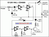 Portable loads such as video cameras, halogen flood lights, electrical irons, hand drillers, grinders, and cutters are powered by connecting long 2- or 3-core cables to the mains plug. Due to prolonged usage, the power cord wires are subjected to mechanical strain and stress, which can lead to internal snapping of wires at any point. In such a case most people go for replacing the core/cable, as finding the exact location of a broken wire is difficult....
[read more]
 This circuit is not a novelty, but it proved so useful, simple and cheap that it is worth building. When the positive (Red) probe is connected to a DC positive voltage and the Black probe to the negative, the Red LED will illuminate. Reversing polarities the Green LED will illuminate. Connecting the probes to an AC source both LEDs will go on....
[read more]
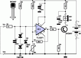 Having good contacts is important – not only in your daily life, but also in electronics. In contrast to social contacts, the reliability of electrical contacts can be checked quickly and easily. Various types of continuity testers are commercially available for this purpose. Most multimeters also have a continuity test function for electrical connections. A simple beep helps you tell good contacts from bad ones....
[read more]
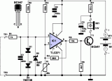 This simple circuit tests speakers, microphones, transformers and voltage. It's basically a very low frequency oscillator that produces extremely short 'fruity' pulses. The type of sound produced is very easy to hear and to determine the precise direction it is coming from, thus making it ideal for checking the phasing in multiple speaker installations. It is also very useful for car stereo installations as well as public address systems where it can drive dozens of speakers directly on a 100V or 70V line system....
[read more]
 Many times we have found itself in the necessity to use a Zener diode and cannot to know the voltage of operation. Many times we cannot read the characteristics or the type that is written on her....
[read more]
 Zener Diode Tester...
[read more]
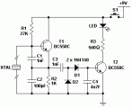 This is a simple XTal tester circuit. T1 and XTal have formed an oscillator. C1 and C2 are voltage divider for oscillator. if the XTal is safe, the oscillator will work well and its output voltage will be rectified by C3, C4, D1 and D2, then T2 will run and LED will light. The circuit is suitable to test 100KHz - 30MHz Xtal....
[read more]
 This circuit is not a novelty, but it proved so useful, simple and cheap that it's worth building....
[read more]
 This simple circuit has helped me out on many occasions. It is able to check transistors, in the circuit, down to 40 ohms across the collector-base or base-emitter junctions. It can also check the output power transistors on amplifier circuits....
[read more]
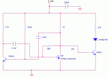 This is a variation on the astable multivibrator. Circuit was recently developed to test for N-mosfets(the power kind e.g irf830)...
[read more]
 This simple circuit generates narrow pulses at about 700-800Hz frequency. The pulses, containing harmonics up to the MHz region, can be injected into audio or radio-frequency stages of amplifiers, receivers and the like for testing purposes....
[read more]
 A low resistance ( 0.25 - 4 ohm) continuity tester for checking soldered joints and connections....
[read more]
 A simple test circuit to fault find audio and radio equipment. Can be used to inject a square wave signal, rich in harmonics, or used with headphones as an audio tracer....
[read more]
 This low voltage circuit can be used to monitor batteries and other volatile sources of current for problems. The circuit sounds an alarm and lights an LED, but can be interfaced to any number of other circuits for many different uses....
[read more]
 This circuit enables you to test quartz resonators at the range values from 32kHz to 24MHz. Confirmation of good state of quartz resonator is done by diode signalling LED and acoustic signal...
[read more]
 This is a simple servo tester which will comprehensively test the capabilities of almost any modern servo. It has two pushbuttons, CENTRE and SWEEP and a potentiometer which works as follows:
- CENTRE Does exactly that, centers the servo, afterwards the potentiometer determines position.
- SWEEP Sweeps the servo back and forth at a rate determined by the potentiometer setting....
[read more]
 This circuit runs a fast battery test without the need of power supply or expensive moving-coil voltmeters. It has two ranges: when SW1 is set as shown in the circuit diagram, the device can test 3V to 15V batteries. When SW1 is switched to the other position, only 1.5V cells can be tested....
[read more]
 This circuit is a Logic Probe. It indicates the logic state of the node of any TTL logic circuit. To do that, we have to supply the probe with the same power of the circuit that we want to analyse: same Vcc and same GND. To check the logic level, we must connect the "Test" wire of the probe to the desired node of the circuit that we want to check....
[read more]
 This is a simple use of the PIC 16F84 about a diode tester....
[read more]
 This circuit uses a CA3420 BiMOS op amp to form a picoammeter with 4 ranges. The exceptionally low input current (typically 0.2pA) makes the CA3420 highly suited for use in a picoammeter circuit. Input transient protection is provided by the 1 megohm resistor in series with the input....
[read more]
 Measures 10mV to 50Volt RMS in eight ranges
Simply connect to your Avo-meter set @ 50uA range...
[read more]