similar circuits
- Hearing Aid
- Amplified Ear
- A Low Cost Hearing Aid
- Studio Series Stereo Headphone Amplifier
- Stereo Headphone Amplifier Circuit Schematic
- Pure Class-A Headphone Amplifier Schematic
- Portable Headphone Amplifier Circuit
- A Hiqh Quality Headphone Amplifier Schematic
- Ultra-High Fidelity High Power Amplifier Reference Design
- Speach Amplifier
- DC-Coupled Audio Amplifier
- A Low Power Wireless Audio Power Amplifier
- 8 Watt Audio Power Amplifier Schematic
- 7 Watt Audio Power Amplifier Circuit Schematic
- 60 Watt Audio Power Amplifier Circuit Diagram
Stereo Headphone Amplifier Circuit Schematic
Description
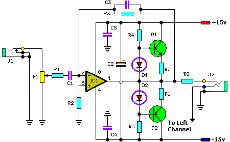
Firstly, I'd like to stress that the intended use of this circuit is only one of many possible applications. Apart from the obvious usage as a headphone amplifier, the circuit can be used for a range of applications where a wide bandwidth low power amplifier is needed. The circuit is based on an opamp, with its output current boosted by a pair of transistors.
The bias diodes should be 1N914 or similar - power diodes are not recommended, as their forward voltage is too low. This may result in distortion around the crossover region, where one transistor turns off and the other on. Credit for this circuit goes to SiliconChip.
Picture of the circuit:
Parts layout:
PCB layout:
Circuit diagram:
Parts List:
- P1 = 50K
- R1 = 56K
- R2 = 22K
- R3 = 330K
- R4 = 10K
- R5 = 10K
- R6 = 33R
- R7 = 33R
- R8 = 68R
- C1 = 0.27uF
- C2 = 10uF-35V
- C3 = 5pF
- C4 = 100nF-63V
- C5 = 100nF-63V
- D1 = 1N914
- D2 = 1N914
- Q1 = BC338
- Q2 = BC328
- IC1 = TL072
- J1 = Audio Input Socket
- J2 = Stereo Headphone Socket
Performance of Prototype:
- Output level == 90mR (max) into 8W headphones
- Input sensitivity == 0.83V RMS for full power
- Frequency response == 0.5dB down at 30Hz and 20kHz
- Signal-to-noise ratio == -95dB unweighted (20Hz to 20kHz) with respect to 500mV input signal
- Separation between channels = = -50dB between 20Hz and 10kHz


