Audio Peak Indicator
Description
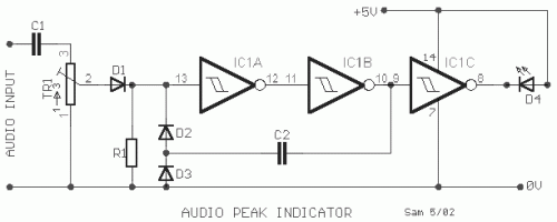
A peak level indicator when a signal exceeds a certain maximum value. It can be quite useful, for instance, with tape recorders, mixing consoles etc. One of the most important requirements of a peak level indicator is that it should respond to very short signals. The circuit is built using a CMOS inverting Schmitt trigger type 74C14. The input impedance of the peak indicator is fairly high. The value depends to some extent on the position of TR1. The unit functions as follows. The input is half- wave rectified by D1. When the voltage across R1 exceeds the upper trigger threshold, a logic [H] is produced at the output of the second Schmitt trigger. The trigger threshold depends on the supply voltage. With a 5V supply the trigger level is 3.6V. The positive pulse at the output of the second trigger is feedback to the input via C2. If the input signal was very short, the logic H level will be maintained during the charging time of C2. This time is determined by the values of C2 and R1. During this time the output of the third trigger is logic L, so that LED D4 lights up as an indication that the level of the input signal is too high. The TR1 trimmer is adjusted to the maximum desired level that the peak indicator should begin to function at.
Circuit diagram
Part List
- R1=1Mohms
- TR1=1Mohms trimmer
- C1=100nF 100V MKT
- C2=150nF 100V MKT
- D1-2-3=1N4148
- D4=RED LED DIODE
- IC1=74C14
