AC Line powered LEDs
Description
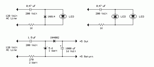
The circuit below illustrates powering a LED (or two) from the 120 volt AC line using a capacitor to drop the voltage and a small resistor to limit the inrush current. Since the capacitor must pass current in both directions, a small diode is connected in parallel with the LED to provide a path for the negative half cycle and also to limit the reverse voltage across the LED. A second LED with the polarity reversed may be subsituted for the diode, or a tri-color LED could be used which would appear orange with alternating current. The circuit is fairly efficient and draws only about a half watt from the line. The resistor value (1K / half watt) was chosen to limit the worst case inrush current to about 150 mA which will drop to less than 30 mA in a millisecond as the capacitor charges. This appears to be a safe value, I have switched the circuit on and off many times without damage to the LED. The 0.47 uF capacitor has a reactance of 5600 ohms at 60 cycles so the LED current is about 20 mA half wave, or 10 mA average. A larger capacitor will increase the current and a smaller one will reduce it. The capacitor must be a non-polarized type with a voltage rating of 200 volts or more.
The lower circuit is an example of obtaining a low regulated voltage from the AC line. The zener diode serves as a regulator and also provides a path for the negative half cycle current when it conducts in the forward direction. In this example the output voltage is about 5 volts and will provide over 30 milliamps with about 300 millivolts of ripple. Use caution when operating any circuits connected directly to the AC line.
