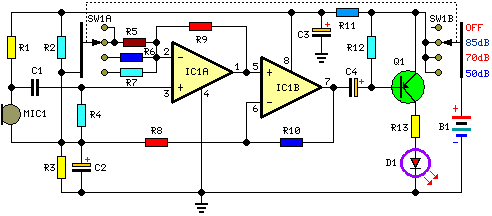
Room Noise Detector Circuit Schematic
Description
This circuit is intended to signal, through a flashing LED, the exceeding of a fixed threshold in room noise, chosen from three fixed levels, namely 50, 70 & 85 dB. Two Op-amps provide the necessary circuit gain for sounds picked-up by a miniature electret microphone to drive a LED. With SW1 in the first position the circuit is off. Second, third and fourth positions power the circuit and set the input sensitivity threshold to 85, 70 & 50 dB respectively. Current drawing is 1mA with LED off and 12-15mA when the LED is steady on.
Circuit diagram:
Parts:
- R1 = 10K
- R2 = 22K
- R3 = 22K
- R4 = 100K
- R5 = 56K
- R6 = 5.6K
- R7 = 560R
- R8 = 2.2K
- R9 = 56K
- R10 = 56K
- R11 = 1K
- R12 = 33K
- R13 = 330R
- C1 = 100nF-63V
- C2 = 10µF-25V
- C3 = 470µF-25V
- C4 = 47µF-25V
- D1 = 5mm. Red LED
- Q1 = BC327
- B1 = 9V PP3 Battery
- SW1 = 2 poles 4 ways rotary switch
- IC1 = LM358 Low Power Dual Op-amp
- MIC1 = Miniature electret microphone
Use:
- Place the small box containing the circuit in the room where you intend to measure ambient noise.
- The 50 dB setting is provided to monitor the noise in the bedroom at night. If the LED is steady on, or flashes bright often, then your bedroom is inadequate and too noisy for sleep.
- The 70 dB setting is for living-rooms. If this level is often exceeded during the day, your apartment is rather uncomfortable.
- If noise level is constantly over 85 dB, 8 hours a day, then you are living in a dangerous environment.
