Solar Panel Based Charger And Small LED Lamp
Description
You can save on your electricity bills by switching to alternative sources of power. The photovoltaic module or solar panel described here is capable of delivering a power of 5 watts. At full sunlight, the solar panel outputs 16.5V. It can deliver a current of 300-350 mA. Using it you can charge three types of batteries: lead acid, Ni-Cd and Li-ion. The lead-acid batteries are commonly used in emergency lamps and UPS. The working of the circuit is simple.
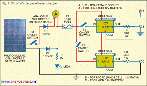
The output of the solar panel is fed via diode 1N5402 (D1), which acts as a polarity guard and protects the solar panel. An ammeter is connected in series between diode D1 and fuse to measure the current flowing during charging of the batteries. As shown in Fig. 1, we have used an analogue multimeter in 500mA range. Diode D2 is used for protection against reverse polarity in case of wrong connection of the lead-acid battery.
Charger circuit diagram:
When you connect wrong polarity, the fuse will blow up. For charging a lead-acid battery, shift switch S1 to ‘on’ position and use connector ‘A.’ After you connect the battery, charging starts from the solar panel via diode D1, multimeter and fuse. Note that pulsating DC is the best for charging lead-acid batteries. If you use this circuit for charging a lead-acid battery, replace it with a normal pulsating DC charger once a week.
Keep checking the water level of the lead-acid battery. Pure DC voltage normally leads to deposition of sulphur on the plates of lead-acid batteries. For charging Ni-Cd cells, shift switches S1 and S3 to ‘on’ position and use connector ‘B.’ Regulator IC 7806 (IC1) is wired as a constant-current source and its output is taken from the middle terminal (normally grounded). Using this circuit, a constant current goes to Ni-Cd cell for charging.
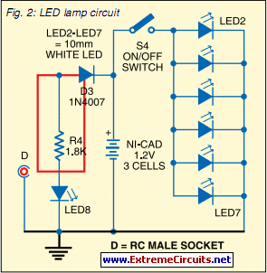
Small LED lamp circuit diagram:
A total of four 1.2V cells are used here. Resistor R2 limits the charging current. For charging Li-ion battery (used in mobile phones), shift switches S1 and S2 to ‘on’ position and use connector ‘C.’ Regulator IC 7805 (IC2) provides 5V for charging the Li-ion battery. Using this circuit, you can charge a 3.6V Li-ion cell very easily. Resistor R3 limits the charging current. Fig. 2 shows the circuit for a small LED-based lamp. It is simple and low-cost.
Six 10mm white LEDs (LED2 through LED7) are used here. Just connect them in parallel and drive directly by a 3.6V DC source. You can use either pencil-type Ni-Cd batteries or rechargeable batteries as the power source. Assemble the circuit on a general-purpose PCB and enclose in a small box. Mount RCA socket on the front panel of the box and wire RCA plug with cable for connecting the battery and LED-based lamp to the charger.
circuit from http://www.extremecircuits.net/2010/05/solar-panel-based-charger-and-small-led.html

