- Long Delay Timer Circuit Diagram
- Jogging Timer Circuit Diagram
- Amplifier Timer Circuit Schematic
- A Very Useful Timed Beeper Circuit Schematic
- A Bedside Lamp Timer Circuit Schematic
- Safety Guard
- Midnight Security Light Circuit Schematic
- Power-Off Time Delay Relay
- Power-On Time Delay Relay
- Generating a Delayed Pulse Using The 555 Timer
- 555 timer Mono stable (one shot) circuit
- Generating Long Time Delays
- Low Voltage, High Current Time Delay Circuit
- 9 Second Digital Readout Countdown Timer
- 9 Second LED Timer and Relay Circuit
555 timer Mono stable (one shot) circuit
Description
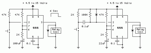
The two circuits below illustrate using the 555 timer to close a relay for a predetermined amount of time by pressing a momentary N/O push button. The circuit on the left can be used for long time periods where the push button can be pressed and released before the end of the timing period. For shorter periods, a capacitor can be used to isolate the switch so that only the initial switch closure is seen by the timer input and the switch can remain closed for an unlimited period without effecting the output.
In the idle state, the output at pin 3 will be at ground and the relay deactivated. The trigger input (pin 2) is held high by the 100K resistor and both capacitors are discharged. When the button is closed, the 0.1uF cap will charge through the button and the 100K resistor which causes the voltage at pin 2 to move low for a few milliseconds. The falling voltage at pin 2 triggers the 555 and starts the timing cycle. The output at pin 3 immediately moves up to near the supply voltage (about 10.4 volts for a 12 volt supply) and remains at that level until the 22 uF timing capacitor charges to about 2/3 of the supply voltage (about 1 second as shown). Most 12 volt relays will operate at 10.4 volts, if not, the supply voltage could be raised to 13.5 or so to compensate. The 555 output will supply up to 200mA of current, so the relay could be replaced with a small lamp, doorbell, or other load that requires less than 200mA. When the button is released, the 0.1uF capacitor discharges through the 100K and 2K resistors. The diode across the 100K resistor prevents the voltage at pin 2 from rising above the supply voltage when the cap discharges. The 2K resistor in series with the 22uF cap limits the discharge current from pin 7 of the timer. This resistor may not be necessary, but it's a good idea to limit current when discharging capacitors across switch contacts or transistors.
