- Long Delay Timer Circuit Diagram
- Jogging Timer Circuit Diagram
- Amplifier Timer Circuit Schematic
- A Very Useful Timed Beeper Circuit Schematic
- A Bedside Lamp Timer Circuit Schematic
- Safety Guard
- Midnight Security Light Circuit Schematic
- Power-Off Time Delay Relay
- Power-On Time Delay Relay
- Generating a Delayed Pulse Using The 555 Timer
- 555 timer Mono stable (one shot) circuit
- Generating Long Time Delays
- Low Voltage, High Current Time Delay Circuit
- 9 Second Digital Readout Countdown Timer
- 9 Second LED Timer and Relay Circuit
Power-On Time Delay Relay
Description
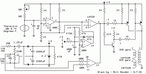
Below is a thermostat circuit I recently built to control a 1300 watt space heater. The heater element (not shown) is connected in series with two back to back 16 amp SCRs (not shown) which are controlled with a small pulse transformer. The pulse transformer has 3 identical windings, two of which are used to supply trigger pulses to the SCRs, and the third winding is connected to a PNP transistor pair that alternately supply pulses to the transformer at the beginning of each AC half cycle. The trigger pulses are applied to both SCRs near the beginning of each AC half cycle but only one conducts depending on the AC polarity.
DC power for the circuit is shown in the lower left section of the drawing and uses a 1.25uF, 400 volt non-polarized capacitor to obtain about 50mA of current from the AC line. The current is rectified by 2 diodes and used to charge a couple larger low voltage capacitors (3300uF) which provide about 6 volts DC for the circuit. The DC voltage is regulated by the 6.2 volt zener and the 150 ohm resistor in series with the line limits the surge current when power is first applied.
The lower comparator (output at pin 13) serves as a zero crossing detector and produces a 60 Hz square wave in phase with the AC line. The phase is shifted slightly by the 0.33 uF, 220K and 1K network so that the SCR trigger pulse arrives when the line voltage is a few volts above or below zero. The SCRs will not trigger at exactly zero since there will be no voltage to maintain conduction.
The upper two comparators operate in same manner as described in the "Electronic thermostat and relay" circuit. A low level at pin 2 is produced when the temperature is above the desired level and inhibits the square wave at pin 13 and prevents triggering of the SCRs. When the temperature drops below the desired level, pin 2 will move to an open circuit condition allowing the square wave at pin 13 to trigger the SCRs.
The comparator near the center of the drawing (pins 8,9,14) is used to allow the heater to be manually run for a few minutes and automatically shut off. A momentary toggle switch (shown connected to a 51 ohm resistor) is used to discharge the 1000uF capacitor so that pin 2 of the upper comparator moves to a open circuit state allowing the 60 Hz square wave to trigger the SCRs and power the heater. When the capacitor reaches about 4 volts the circuit returns to normal operation where the thermistor controls the operation. The momentary switch can also be toggled so that the capacitor charges above 4 volts and shuts off the heater if the temperature is above the setting of the pot.
