PIC diode tester
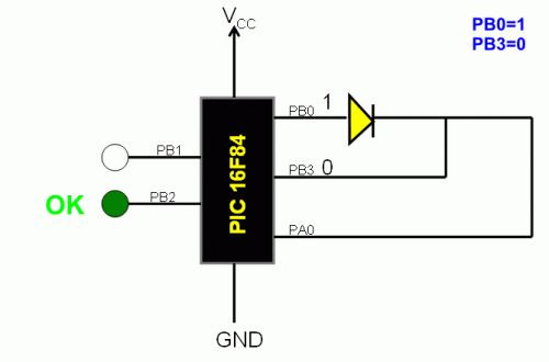
This is a simple use of the PIC 16F84 about a diode tester.
Circuit diagram
Test procedure : We set «1» to PB0 and «0» to PB3. If diode is ok and opens, then at PA0 we have «1». If PA0 is «0», then the the diode has problem. With the program we manage what the PIC will do in each situation . If PA0 is «1», green led lights wich means that the diode is OK and if PA0 is «0» red led is lighting and the diode is problematic Test continuous as follows: We give «0» at PB0 and «1» to PB3. If diode is OK and opens, then at PA0 is «1». If PA0 is «0», then diode has problem. If PA0 is «1», green led lights that means that diode is OK and if PA0 is «0» the red diode is lights that means the the diode is problematic.
Source Code
author: Manolis Xenias, manolis_the_master@yahoo.gr
circuit from http://www.electronics-lab.com/
circuit from http://www.electronics-lab.com/

