similar circuits
- Long Delay Timer Circuit Diagram
- Jogging Timer Circuit Diagram
- Amplifier Timer Circuit Schematic
- A Very Useful Timed Beeper Circuit Schematic
- A Bedside Lamp Timer Circuit Schematic
- Safety Guard
- Midnight Security Light Circuit Schematic
- Power-Off Time Delay Relay
- Power-On Time Delay Relay
- Generating a Delayed Pulse Using The 555 Timer
- 555 timer Mono stable (one shot) circuit
- Generating Long Time Delays
- Low Voltage, High Current Time Delay Circuit
- 9 Second Digital Readout Countdown Timer
- 9 Second LED Timer and Relay Circuit
A Tan Timer Circuit Diagram
Description
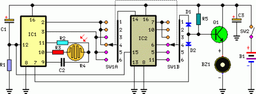
This timer was designed for people wanting to get tanned but at the same time wishing to avoid an excessive exposure to sunlight. A Rotary Switch sets the timer according to six classified Photo-types (see table). A Photo resistor extends the preset time value according to sunlight brightness (see table). When preset time ends, the beeper emits an intermittent signal and, to stop it, a complete switch-off of the circuit via SW2 is necessary.
Circuit diagram:
Parts:
- R1 = 47K - 1/4W Resistor
- R2 = 1M - 1/4W Resistor
- R3 = 120K - 1/4W Resistors
- R4 = Photo resistor (any type)
- R5 = 120K - 1/4W Resistors
- C1 = 10µF - 25V Electrolytic Capacitors
- C2 = 220nF - 63V Polyester Capacitor
- C3 = 10µF - 25V Electrolytic Capacitors
- D1 = 1N4148 - 75V 150mA Diodes
- D2 = 1N4148 - 75V 150mA Diodes
- Q1 = BC337 - 45V 800mA NPN Transistor
- B1 = 3V Battery (two 1.5V AA or AAA cells in series)
- IC1 = 4060 - 14 stage ripple counter and oscillator IC
- IC2 = 4017 - Decade counter with 10 decoded outputs IC
- SW1 = 2 poles 6 ways Rotary Switch (see notes)
- SW2 = SPST Slider Switch
- BZ1 = Piezo sounder (incorporating 3KHz oscillator)
Notes:
- Needing only one time set suitable for your own skin type, the rotary switch can be replaced by hard-wired links.
- A DIP-Switch can be used in place of the rotary type. Please pay attention to use only one switch at a time when the device is off, or the ICs could be damaged.
